ロッキングカーブ
ロッキングカーブ
rocking curve
[目次:理論(電子の散乱/回折/結像)]
回折条件(励起誤差)の変化に対する回折強度の変化曲線。通常はブラッグ条件を満たす入射角の周りで入射方向を変えたときの強度変化の曲線のことを指す。
試料が非常に薄い場合のロッキングカーブは運動学的回折理論によって説明される。試料が厚くなると(おおよそ厚さ数nm以上)動力学的回折効果(多重回折効果)を反映したロッキングカーブになる。通常、観察されるロッキングカーブは動力学的回折効果を反映したロッキングカーブであり、運動学的なロッキングカーブが観察されることはほぼない。ロッキングカーブは収束電子回折(CBED)図形で観察することができる。
図1に、運動学的回折理論によって計算した回折波(反射波)のロッキングカーブ(a)と、二波近似動力学理論を用いて計算した回折波のロッキングカーブ(b)を示す。運動学的回折では、主極大の高さは厚さtの2乗に比例して大きくなり、その半値幅はtの逆数に比例して小さくなる。副極大は厚さとともに急激に小さくる。厚さが数nm以上では副極大は無視できる大きさになり、主極大しか観測されない。これに対して、動力学的回折では、厚さが増しても主極大は一定値に留まる。副極大の大きさと角度広がりは図に示したような包絡線に沿って変化する。包絡線の半値幅は、消衰距離ξgの逆数に比例する。図の例から分かるように、回折強度はブラッグ反射を丁度満たす位置で最大になるとは限らない。
図2(a)に、収束電子回折法によって得られたSiの220反射のロッキングカーブを示す。220反射のロッキングカーブは、計算したロッキングカーブ(図1(b))をよく再現している。なお、図の周辺に見られる黒い線は、励起されている他の反射に由来する。
参考までに図2(b)に、[100]晶帯軸入射で撮られた透過波000の収束電子回折図形を示す。ここでは、220反射に直交する220反射の効果で、直交する2方向にロッキングカーブが見られる。また、この図形から、Siの結晶が[100]軸に関して4回の回転対称性を持つことがわかる。
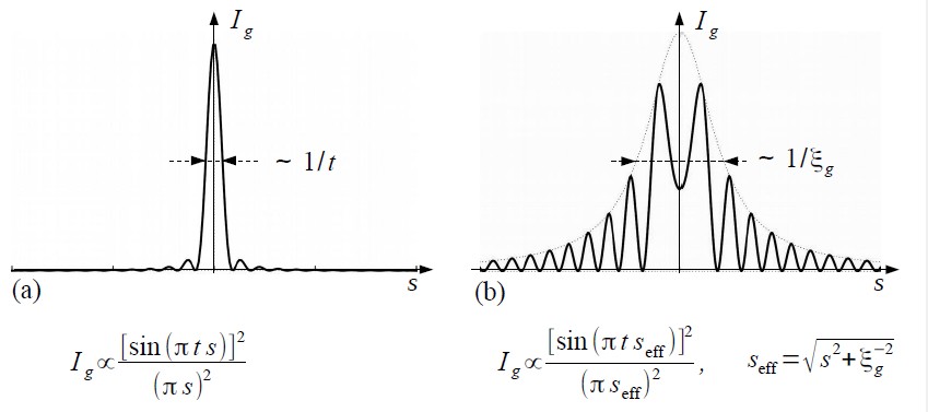
図1 (a) 運動学的回折による回折波のロッキングカーブ。(b)動力学的回折による回折波のロッキングカーブ。記号tは試料の厚さ、sはブラッグ条件からのはずれの量(励起誤差)、ξgは消衰距離。図の下に、運動学的回折および動力学的回折による回折波の強度式を示した。“やさしい電子回折と初等結晶学”共立出版より転載
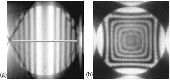
図2 (a)二波近似条件で撮られたSiの220反射のロッキングカーブ。中央の横線に沿ってトレースした強度曲線は図1(b)の曲線と良い一致を示している。両端に見える斜めに走る線はほかの反射に由来する。(b)[100]晶帯入射で撮られた透過波000のロッキングカーブを参考までに示した。4回の回転対称性が奇麗に見えている。“やさしい電子回折と初等結晶学”共立出版より転載
A “rocking curve” means the change in diffraction intensity as a function of the change of diffraction condition (excitation error). It usually refers to the intensity profile obtained when the incident beam direction is changed around the Bragg condition.
For a very thin specimen, the rocking curve is interpreted by the kinematical diffraction theory. For a specimen thicker than a few nanometers, the rocking curve suffers the dynamical diffraction effect (multiple diffraction effect). Thus, the rocking curve usually observed is explained by the dynamical diffraction theory and a purely kinematical rocking curve is rarely observed. Such a rocking curve can be observed in a convergent-beam electron diffraction (CBED) pattern.
Fig. 1 shows a rocking curve of a diffracted (reflected) wave calculated by the kinematical diffraction theory (a), and that calculated by the two-wave dynamical diffraction theory (b). In the case of kinematical diffraction, the magnitude of the principal maximum increases proportional to the square of the thickness t, and the width of the principal maximum decreases proportional to the reciprocal of t. The subsidiary maxima rapidly decrease with increasing thickness. At a thickness of a few nm or more, the magnitude of the subsidiary maxima can be neglected. Thus, only the principal maximum is observed in the rocking curve.
On the other hand, in dynamical diffraction, even if thickness increases, the magnitude of the principal maximum remains at a certain (finite) value. The magnitude and angular broadening of the subsidiary maxima are changed along the envelope shown in Fig. 1(b). The width of the envelope is proportional to the reciprocal of the extinction distance ξg. As is seen in Fig. 1(b), the diffraction intensity does not necessarily take the maximum value at the position of the exact Bragg condition.
Fig. 2(a) shows a rocking curve of the 220 reflection of Si taken by the CBED method. This shows a good agreement with the calculated rocking curve (Fig. 1(b)). It is noted that black lines observed in the peripheral of the figure are due to the other reflections excited.
Fig. 2(b) shows a CBED pattern of the 000 transmitted wave taken at the [100] zone axis incidence. In this figure, two rocking curves are seen in the orthogonal two directions which originate from the orthogonal 220 and 220 reflections. In addition, it is confirmed from the figure that a Si crystal has a four-fold rotational symmetry with respect to the [100] axis.
Fig. 1 (a) Rocking curve of a diffracted wave due to kinematical diffraction. (b) Rocking curve of a diffracted wave due to dynamical diffraction. The symbols t, s, and ξg respectively stand for specimen thickness, deviation parameter (excitation error) from a Bragg condition, and extinction distance. The intensity equations of the diffracted wave which are obtained respectively by kinematical diffraction and dynamical diffraction, are given under the figures (a) and (b). (reprinted from M. Tanaka, M. Terauchi, K. Tsuda, “Introduction to Electron Diffraction and Elementary Crystallography” (in Japanese), Kyoritsu Printing Co., Ltd., 2014)
Fig. 2 (a) Rocking curve of the 220 reflection of Si taken under the two-wave approximation condition. The intensity curve traced along the center horizontal line agrees well with the curve shown in Fig. 1(b). The obliquely running dark lines seen at the periphery originate from the other reflections. (b) CBED pattern of the 000 transmitted wave taken at the [100] zone axis incidence. Two orthogonal rocking curves are seen in the vertical and horizontal directions. A four-fold rotational symmetry is clearly seen. (reprinted from M. Tanaka, M. Terauchi, K. Tsuda, “Introduction to Electron Diffraction and Elementary Crystallography” (in Japanese), Kyoritsu Printing Co., Ltd., 2014)
関連用語から探す
説明に「ロッキングカーブ」が含まれている用語


