静電サブフレーミング
静電サブフレーミング
Electrostatic subframing
[目次:理論(電子の散乱/回折/結像)]
静電サブフレーミングは、透過電子顕微鏡法 (TEM) において、試料を透過した電子線を静電偏向器で時系列的および二次元的に偏向し、一回の露光の間にカメラの検出器面上の異なる領域に画像を振り分ける手法である。すなわち、試料の構造変化を観察する際に、一回の画像取得で、複数の時刻に対応するTEM像または電子回折図形を記録できる。したがって、カメラの露光時間 (たとえば数十ミリ秒) の10倍以上速い時間スケール (たとえば数ミリ秒) で起きる構造変化を一枚の画像に時系列的に捉えることができ、時間分解TEM観察における時間分解能の高速化ができる。
カメラの検出器面上に振り分けられたそれぞれの画像はサブフレーム画像と呼ばれる。カメラの受光面全体に記録されるサブフレーム画像の数 (視野の大きさ) は、物理的な制限すなわち静電偏向器の電極の幅または制限視野絞りの大きさによって決まる。サブフレームの大きさは、カメラの受光面全体に対して1/16、1/25、1/49、1/64 (16個 (4×4)、25個 (5×5)、49個 (7×7)、64個 (8×8)) の大きさとなるように設定する。隣接するサブフレーム間には数ミリ秒程度の時間差が生じる。TEM画像の有効フレームレートをサブミリ秒オーダーに向上させるためには、カメラの1フレーム内に記録するサブフレーム画像数をさらに増やす必要があるが、現状では最大8x8程度である。
図1 (a) には、試料を透過した電子線が静電偏向器によって偏向され、カメラの検出器面上に振り分けられる様子を模式図で示した。実際のサブフレーム画像は、図1 (b) に数字で示すような配置になっている。すなわち、静電偏向の左右および縦成分を組み合わせて、画像を検出器面上に余すところなく振り分けられる。記録されたそれぞれのサブフレーム画像は、ひずみ補正と位置合わせ処理したのち、図1 (c) のように並べることでコマ送り画像 (動画) が得られる。
隣り合うフレーム番号のサブフレーム画像は一定の時間差 (切替時間τ) をもつ。図1 (d) に、N (= 16、25、49、64) 個のサブフレーム画像が切り替え時間を伴って1枚目のカメラフレームに記録された後、2枚目のカメラフレームに移る様子を示した。カメラの1フレームの露光時間はT (例:40 ms)、サブフレームの露光時間 t はTのN分の1、ビームの切替時間τは ~50 nsである。サブフレームの露光時間tは数ms以下になるため、高いS/N比を持つサブフレーム画像を得るには、高い電子照射量が必要である。
図2 (a)、(b) は、CeO2ナノ粒子の (111) 表面および (111) 表面構造の時系列変化を1カメラフレーム中に49枚 (7×7) のサブフレームで記録した電顕像から抽出した2枚のTEM像である。1カメラフレームの露光時間Tは40 ms、各サブフレーム像の露光時間tは0.82 msである。最初のサブフレーム像の取得時刻を0 msとすると、2番目の取得時刻は0.82 ms、3番目は1.63 msである。図2 (a) の3番目のTEM像 (1.63 ms) では、CeO2 (111) 表面ステップの原子カラム (白抜き矢印で示した) が不明瞭であり、試料厚み方向に並ぶCe原子列が動いている過程を捉えている。一方、図2 (b) の8番目のTEM像 (5.71 ms) では原子カラムが明瞭に観察され、Ce原子列の動きが収まり、矢印で示したCeO2の原子列の変化が約4 ms後に完了したことを示している。
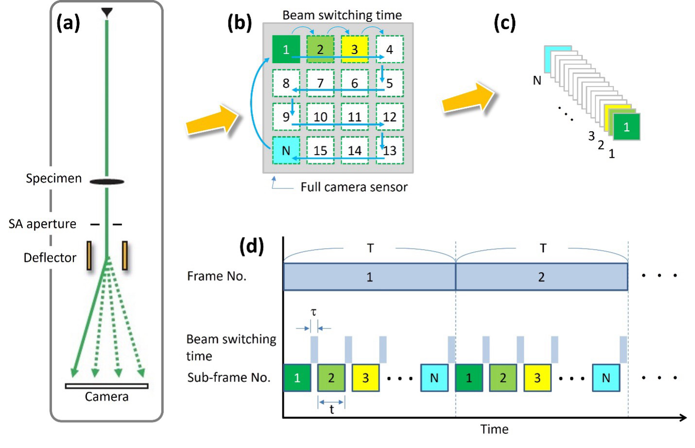
図1 (a) TEM装置での静電偏向器の模式図。(b) 数字で示した順序に静電偏向されて振り分けられたサブフレーム画像の模式図。(c)撮影順に従って並べたサブフレーム画像の模式図。(d) 1つのサブフレームの露光時間はtであり、2つのサブフレームの間にはビーム切替時間τがあることを示す。カメラの1フレームの露光時間はTである。連続するカメラフレーム (フレーム1、フレーム2、・・・) を記録することによって動画として表示することができる。
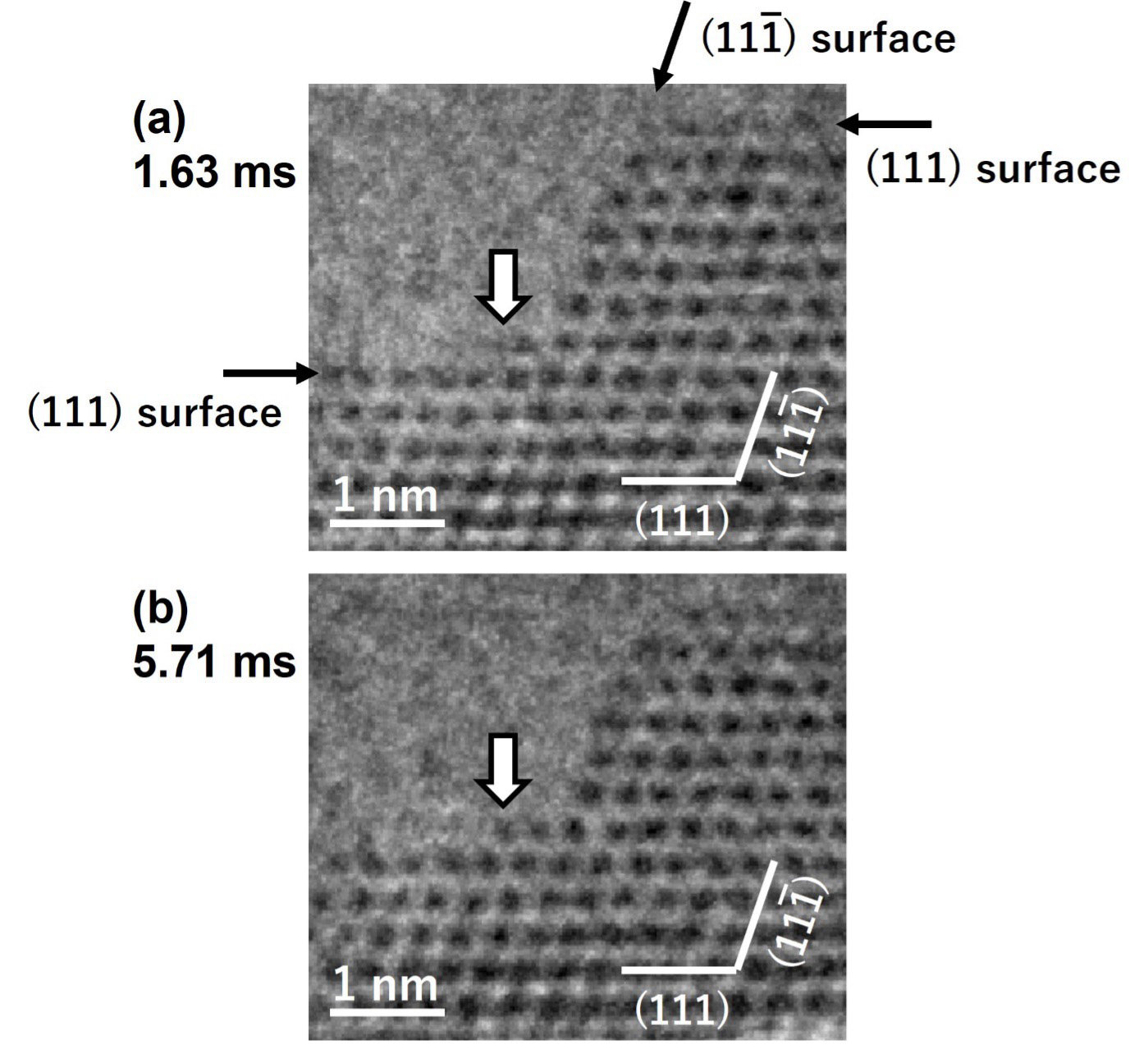
図2 (a) および (b) CeO2ナノ粒子の[110]入射のサブフレームTEM像。
矢印で示した部分:(a) Ce原子列が動いている過程。(b) Ce原子列の動きが収まり、原子カラムが明瞭に観察されている。
Electrostatic sub-framing is a technique in transmission electron microscopy (TEM), in which an electron beam transmitted through a specimen is deflected both sequentially and two dimensionally by an electrostatic deflector, thereby distributing images in different regions (sub-frames) of the camera detector during a single exposure. For observation of structural change of the specimen, this technique enables us to record multiple TEM images or diffraction patterns corresponding to serial time points within a single image acquisition. It allows time-series image acquisition of structural change occurring on a timescale significantly shorter than the camera exposure time (e.g., several milliseconds (ms), more than an order of magnitude faster than a typical exposure of several tens of ms) can be recorded within a single image. Thus, it improves the resolution of time-resolved TEM observations.
Each image allocated to a separate region on the detection plane of the camera is referred to as a sub-frame image. The total number of sub-frame images (size of filed-of-view) recorded on the detection plane of the camera is determined by physical limitations, i.e., the distance of the electrodes of the electrostatic deflector or the diameter of the selected area aperture.
The sub-frame size is adjusted so that it occupies 1/16, 1/25, 1/49, or 1/64 of the entire detector area, corresponding to 16 (4×4), 25 (5×5), 49 (7×7), or 64 (8×8) sub-frames. A temporal offset of several milliseconds arises between adjacent sub frames. In order to achieve the effective frame rate of a TEM image to the order of sub-ms, it is needed to further increase the number of the sub-frames recorded on one camera frame, however, the current maximum is 8×8.
Fig. 1 (a) schematically illustrates how the electron beam passing through a specimen is deflected by the electrostatic deflector and is allocated to the detection plane of the imaging camera. Actual sequence of the sub-frame images is shown numerically in Fig. 1 (b). That is, by combining the horizontal and vertical components of the electrostatic deflection, the images are allocated to the entire detection plane. The recorded sub-frame images are subjected to distortion correction and positional alignment, and then arranged as shown in Fig. 1 (c) to produce frame-by-frame images (a movie).
Each adjacent sub-frame image has a certain time offset (switching time τ). Fig. 1 (d) illustrates how N sub frame images (N = 16, 25, 49, 64) are recorded within the first camera frame with the switching time τ, and then proceed to the second camera frame. The exposure time of one camera frame is T (e.g., 40 ms). The exposure time t of each sub frame is T/N, and the beam switching time τ is approximately 50 ns. Because the sub frame exposure time t becomes less than a few milliseconds, obtaining sub frame images with a high signal to noise ratio requires a high electron dose.
Fig. 2 (a) and (b) show two sub-frame TEM images of the (111) and (111) surface structure change of a CeO2 nanoparticle, extracted from 49 sub frame (7 × 7) images recorded in one camera frame. The exposure time T for one camera frame is 40 ms and the exposure time t for each sub-frame is 0.82 ms. If the acquisition time of the first sub-frame image is defined as 0 ms, those of the second and third images are 0.82 ms and 1.63 ms, respectively. In the third sub-frame image at 1.63 ms (Fig. 2 (a)), the atomic column in the specimen thickness direction indicated by an outlined arrow appearing on the (111) plane of CeO2 is blurred, capturing a process where the Ce atoms aligned along the specimen thickness direction are moving. In contrast, in the eighth image at 5.71 ms (Fig. 2 (b)), the atomic column is clearly observed. These images indicate that the motion of the Ce atomic column has settled down, and the structural change of the Ce atomic column has completed in about 4 ms.
Fig. 1. (a) Schematic illustration of the electrostatic deflector in the TEM system. (b) Schematic diagram of the sub frame images distributed by electrostatic deflection in the numerical order indicated. (c) Schematic diagram of the sub frame images arranged in the order of acquisition. (d) Illustration showing that the exposure time of a single sub frame is t, and that a beam switching time τ exists between two consecutive sub frames. The exposure time of one camera frame is T. By recording successive camera frames (Frame 1, Frame 2, …), the data can be displayed as a movie.
Fig. 2. (a) and (b) Sub frame TEM images of a CeO₂ nanoparticle taken with the [110] incidence. At the position indicated by an outlined arrow, (a) the process in which the Ce atomic row is in motion; (b) the state after the motion has ceased, where the atomic column is clearly resolved.
関連用語から探す
説明に「静電サブフレーミング」が含まれている用語


