ケーラー照明(ケーラー照射)
ケーラー照明(ケーラー照射)
Köhler Illumination
[目次:レンズ系]
コンデンサーミニレンズへの励磁電流を強くし、対物レンズの前方磁場の前焦点面に入射ビームを集束させることにより、電子線を試料に平行に照明(照射)する方法のこと。TEM像(明視野像、暗視野像、HREM像)を得るときに用いられる。試料への平行照射が崩れると、試料の場所によって回折条件が異なることになり、像の解釈に支障をきたすことがある(図1(b))。
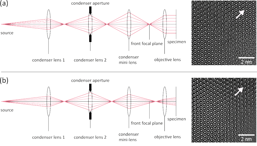
図1(a) 試料への平行照射の光線図、および平行照射で撮影したβ-Si3N4の高分解能TEM像。入射ビームは対物レンズの前方磁場の前焦点面に集束されているので、試料への平行照射が実現されている。視野の全ての場所で同じ結晶構造像が見られる。
(b) 平行照射でない場合の光線図、および平行照射でない照射条件で撮影したβ-Si3N4の高分解能TEM像。入射ビームは対物レンズの前方磁場の前焦点面に集束されていないために、非平行なビームが試料に照射されている。照射の方向が視野の場所ごとに異なるために、結晶構造の見え方が場所によって異なる。矢印で示した場所での像は、図(a)に矢印で示した場所での像とは、明らかに異なっていることが分かる。
近年、クライオEM分野では、図1(a)に示した平行照射に加えてCL絞りのフレネル縞が発生しない照射条件を、光学顕微鏡との類似性から、ケーラー照明と呼ぶようになっている。TEMの照射系は一般にはCL絞りの位置と試料面が対物レンズの前方磁場に対して共役な関係になっていない。そのため、CL絞りの像は対物レンズの前方磁場によって試料上に焦点を結ばず、フレネル縞を伴う照明になり、視野全体が均一になる照明光を作ることができない(図2(a))。CL絞りと試料面が共役な関係になるように、試料の位置と対物レンズの励磁を調整することでフレネル縞のない均一な照明を作ることができる。
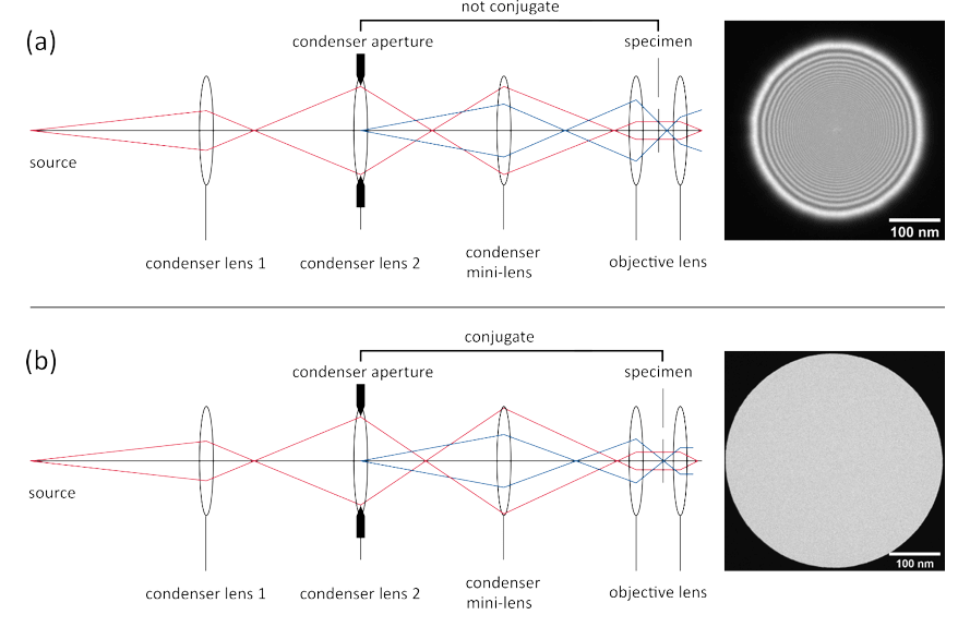
図2(a) 平行照射条件を満たしているが、CL絞りと試料面の位置について注意を払っていない場合の光線図、およびその場合の入射ビームの像。CL絞りと試料面が対物レンズの前方磁場に対して共役な位置にないため、CL絞りの像は対物レンズの前方磁場によって試料上に焦点を結ばず、CL絞りによるフレネル縞が生じている。
(b) 平行照射条件の条件に加えて、CL絞りと試料面が共役になるように、試料位置と対物レンズの励磁を調整した場合の光線図、およびその条件での入射ビームの像。CL絞りと試料面が共益な位置になっているので、フレネル縞のない均一な照明が得られている。
A method of illuminating a parallel electron beam onto a specimen by a strong excitation of the condenser mini lens to focus the incident electron beam onto the front focal plane of the prefield of the objective lens. The illumination is used for the observation of bright-field images, dark-field images and HREM (high-resolution electron microscope) images. If the parallel illumination onto the specimen is not achieved, the diffraction condition becomes different depending on the specimen position (Fig.1(b)), which may mislead interpretation of the image.
Fig. 1(a) Ray path diagram of the parallel illumination onto the specimen and a HREM image of β-Si3N4 taken at a parallel illumination condition. The incident beam is focused onto the front focal plane of the prefield of the objective lens achieving a parallel illumination onto the specimen. As a result, the images of the crystal structure are seen to be the same in all areas of the field of view.
(b) Ray path diagram of non-parallel illumination and a HREM image of β-Si3N4 taken at a non-parallel illumination condition. Since the incident beam is not focused onto the front focal plane of the prefield of the objective lens, the specimen is illuminated with a non-parallel beam. The crystal structure image looks different depending on the area in the field of view because the direction of illumination onto the specimen is different. It can be seen that the structure image indicated by the arrow is clearly different from the image indicated by the arrow in Fig. 1(a).
In recent years, in the cryo-electron microscopy field, the illumination condition without causing Fresnel fringes due to the CL (condenser lens) aperture in addition to parallel illumination shown in Fig 1(a), is called “Köehler illumination” because of its analogue to the technique of light optical microscopy. In the ordinary illumination system of TEM, the position of the CL aperture and the specimen plane are not always conjugate with respect to the prefield of the objective lens. Thus, the image of the CL aperture is not focused on the specimen position by the prefield of the objective lens, causing a non-uniform illumination onto the specimen plane accompanied with Fresnel fringes due to the CL aperture (Fig.2(a)). By adjusting the specimen position and the excitation of the objective lens so that the CL aperture and the specimen take a conjugate position, a uniform illumination without Fresnel fringes is achieved.
Fig. 2. (a) Ray path diagram and the image of the incident beam in the case where the parallel illumination condition is satisfied but no attention is paid to the positions of the CL aperture and the specimen. Since the position of the CL aperture and the specimen plane are not conjugate with respect to the prefield of the objective lens, the image of the CL aperture is not focused on the specimen position by the prefield of the objective lens. Then, Fresnel fringes due to the CL aperture are formed on the specimen plane (image plane).
(b) Ray path diagram and the image of the incident beam obtained by adjusting the specimen position and the excitation of the objective lens so that the CL aperture and the specimen are conjugate, in addition to the parallel illumination condition. Since the CL aperture and the specimen positions are conjugate with respect to the prefield of the objective lens, a uniform illumination without Fresnel fringes is achieved.
関連用語から探す
説明に「ケーラー照明(ケーラー照射)」が含まれている用語


