高分解能電子顕微鏡法
高分解能電子顕微鏡法
high-resolution electron microscopy, HREM
[目次:理論(電子の散乱/回折/結像)]
透過電子顕微鏡で、薄い試料からの透過波と回折波を干渉させて高分解能TEM像すなわち格子像や結晶構造像を得る手法。
電子線の入射方向を晶帯軸に正確に合わせ、対物レンズのフォーカスをシェルツァー・フォーカス条件に合わせると、結晶の構造をよく表す像が得られる。像の分解能は対物レンズの球面収差や入射電子線の加速電圧に依存する。
対物レンズの球面収差補正装置を搭載しない場合、結晶構造像は対物レンズの正の球面収差の影響を最適化するために、シェルツァー・フォーカス条件(不足焦点:アンダーデフォーカス)で撮像される。
一方、球面収差補正装置を搭載した透過電子顕微鏡を用いる場合、元々存在する対物レンズの正の球面収差を補正してゼロにも負にもすることができる。そのため、撮像の際のフォーカス条件は、球面収差係数で定められるフォーカス設定値(シェルツァー・フォーカス条件)にとらわれず、フォーカス条件を変えながら、視認あるいはコンピューターシミュレーションでコントラストが最適と判断した条件で撮像する。
下図には、球面収差補正装置を搭載した透過電子顕微鏡を用いて、不足焦点(アンダーフォーカス)条件と過焦点(オーバーフォーカス)条件に設定して撮影した高分解能TEM像を示す。
試料が厚い場合には動力学的回折の影響のために、得られた像は結晶の構造に直接は対応しなくなる。HAADF-STEM像では動力学効果が抑えられるため、像の解釈の信頼性は高くなる。結晶構造や界面、格子欠陥などの構造の解析に利用される。
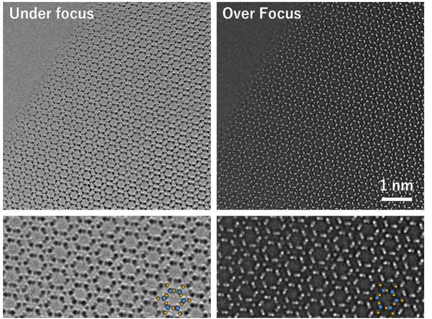
図 球面収差補正装置を搭載した透過電子顕微鏡を用いて取得した[0001]入射β-Si3N4の高分解能電子顕微鏡像と一部拡大像。試料端の非常に薄い領域を観察している。拡大図内に示す青丸はシリコン、黄色丸は窒素の原子位置を示す。不足焦点、過焦点で明暗のコントラストが反転していることが分かる。なお、図の左上部は試料の無い真空領域である。
A technique of transmission electron microscopy to obtain a high-resolution electron microscope (HREM) image, that is, a lattice image or a crystal structure image, from a thin specimen by utilizing wave interference between transmitted and diffracted waves.
An image which corresponds to the crystal structure is obtained by precisely adjusting the incident beam orientation to a zone axis of the crystal and by setting the focus of the objective lens to Scherzer focus. The spatial resolution of the image depends on the coefficient Cs of the objective lens and the accelerating voltage of the incident beam.
When a TEM not equipped with a Cs corrector is used, a HREM image or a crystal structure image is taken at the Scherzer focus condition (under-defocus) to optimize the effects of the spherical aberration of and the defocus of the objective lens.
When a TEM equipped with a Cs corrector is used, the original positive value of Cs can be adjusted to zero or a negative value. Thus, the focus condition for imaging is not limited by the Scherzer focus condition. The HREM image can be taken under an appropriate focus condition where the image contrast is optimal by a visual check and by prior computer simulations while changing the focus condition.
The figures below show HREM images taken with a TEM equipped with a Cs corrector, in which the focus was set to an under-focus condition and an over-focus condition.
When the specimen is thick (more than 10 nm), the image obtained does not well correspond to the crystal structure due to the dynamical diffraction effect. In HAADF-STEM images, the dynamical diffraction effect is suppressed and the reliability of the image interpretation is higher.
HREM images are used for analysis of crystal structures and lattice detects, including interface structures.
Fig. HREM images of β-Si3N4 taken at the [0001] incidence with a TEM equipped with a Cs corrector, and their partial enlarged images (lower two images). These were taken from a very thin region at the edge of the specimen. Blue circles and yellow circles in the enlarged images (lower) indicate respectively silicon atoms and nitrogen atoms. Bright or dark contrast is reversed between the images of under-focus and over-focus. The upper left part in each top image is a vacuum region without specimen.
関連用語から探す
説明に「高分解能電子顕微鏡法」が含まれている用語


