コンデンサー・オブジェクティブレンズ
コンデンサー・オブジェクティブレンズ
condenser-objective lens (C-O lens)
[目次:レンズ系]
対物レンズの前方磁場をコンデンサーレンズとして作用させ電子線を試料上に絞って照射し、後方磁場で結像するレンズ。
C-Oレンズのギャップ間に作られる光軸上の磁場のピークは、図1に赤線で示すように1つであるが、磁場が強いため、図2の薄茶色の楕円で示すように2枚のレンズとして働く。入射する電子線は黄色線で示すように、前方磁場(第1のレンズ)で大きく集束され、試料面上に微小プローブを作る。この前方磁場によるプローブの縮小率は~1/100である。C-Oレンズによる入射ビームサイズの縮小は、STEM像の分解能の向上やCBEDの照射領域の微小化およびEDS・EELSの分析領域の微小化に不可欠である。後方磁場(第2のレンズ)で縮小されたプローブの拡大像が観察される。
原子像を含む高分解能電顕像観察(HREM)には、試料に平行ビーム照射する必要がある。その場合には、コンデンサーミニレンズを用いて入射ビームをC-Oレンズの前方磁場の焦点に収束させ、試料上で光軸に平行なビームを作る(図3の右図)。試料を透過した電子線は、後方磁場で拡大され、中間レンズの前方に像を作る。その像は、結像系レンズ(中間および投影レンズ)によってさらに拡大され、スクリーン上に投影される。
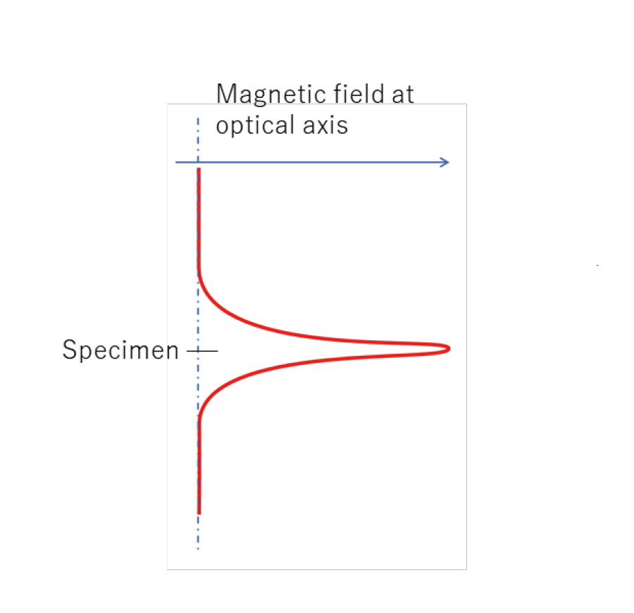
図1. C-Oレンズにおける光軸上の磁場分布の模式図
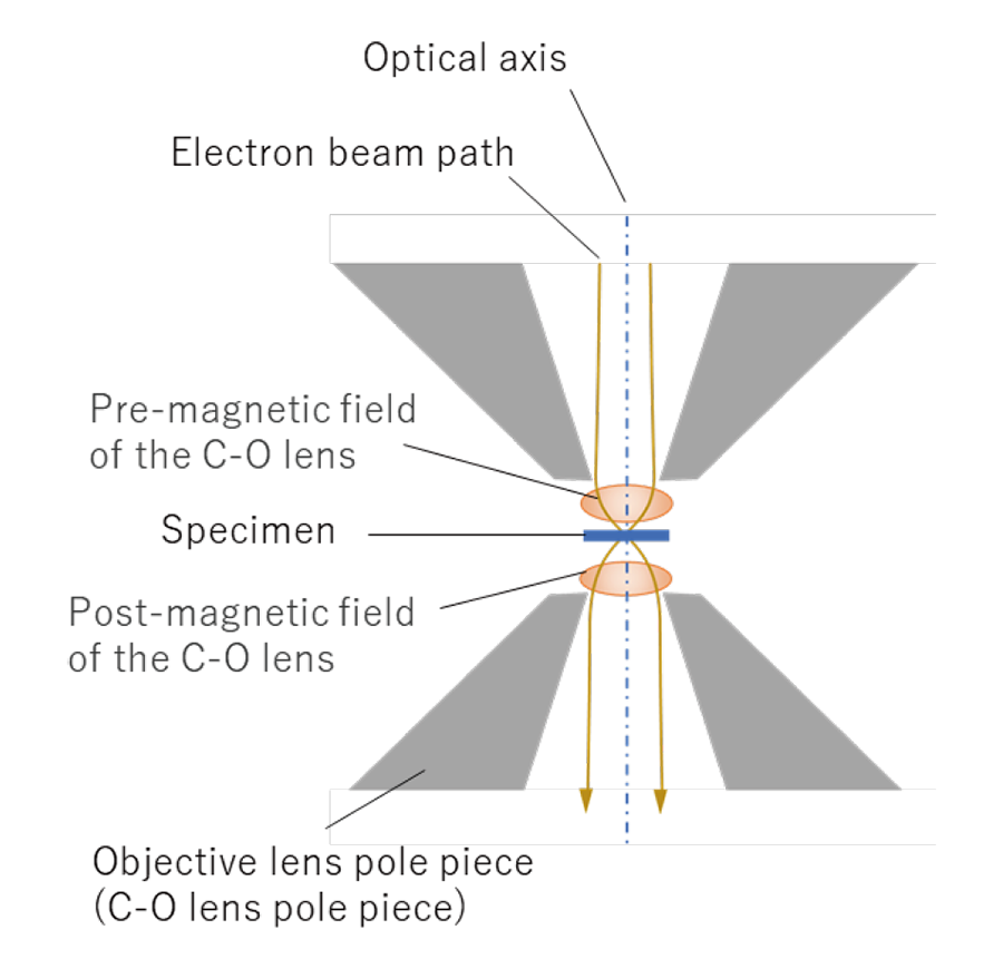
図2. C-Oレンズにおける前方磁場と試料と後方磁場の位置関係。黄色い縦の線はSTEMの場合の電子線の光線図の模式図
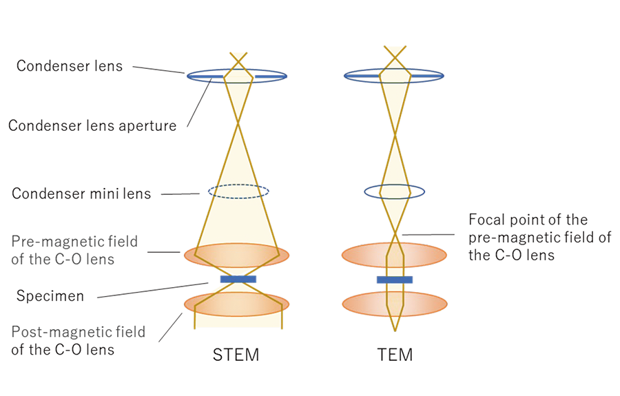
図3. C-Oレンズを用いたとき、(左) STEMの場合の光線図と、(右) TEMの場合に、コンデンサーミニレンズを働かせて、試料上に平行ビームを作るときの光線図
The condenser-objective lens (C-O lens) makes its pre-magnetic field act as a condenser lens for the electron beam to be focused onto a specimen, and makes its post-magnetic field act as an objective lens to form the specimen image on the image plane.
The C-O lens has only one peak of the magnetic field in the gap of the lens as shown by a red line in Fig. 1, but it acts as two lenses because of its strong magnetic field as shown by two brown ellipses in Fig. 2. The incident electron beam is strongly converged by the pre-magnetic field (first lens) as shown by the yellow lines, and the lens demagnifies the size of the incident beam down to ~1/100 to form a small probe on the specimen plane.
Demagnification of the incident beam by the C-O lens is essential for obtaining a high resolution of the STEM image, sub-nanometer-area illumination for CBED and for decreasing the analysis area (sub-nanometer-size) of EDS and EELS. The post-magnetic field (second lens) produces an enlarged image of the focused beam on the specimen.
For observation of the TEM image including a HREM image (atomic level resolution image), parallel beam illumination onto a specimen is required. To produce the parallel beam, a condenser mini lens is used to converge the incident beam onto the focal point of the pre-magnetic field of the C-O lens (right of Fig. 3). The electron beam passing through the specimen is enlarged by the post-magnetic field of the C-O lens and further enlarged with intermediate and projector lenses, and finally a TEM image is formed on the screen.
Fig. 1 Schematic of the distribution of magnetic field along the optical axis of the C-O lens.
Fig. 2 Schematic of the positions of the pre-magnetic field of the C-O lens and the specimen and the post-magnetic field. Vertical yellow lines schematically show ray paths in the STEM mode.
Fig. 3 Left: Ray path of the STEM mode using the C-O lens. Right: Ray path of the TEM mode, where the parallel beam is produced on the specimen using the condenser-mini lens.
関連用語から探す
説明に「コンデンサー・オブジェクティブレンズ」が含まれている用語


