ディフラクトグラムタブロー
ディフラクトグラムタブロー
diffractogram tableau
[目次:理論(電子の散乱/回折/結像)]
入射ビームを1~2度位傾け方位角を次々に変えて撮ったアモルファス試料の高倍像のフーリエ変換図形(diffractogram)を、2次元的に表示したもの。Zemlin tableauとも呼ばれる。このtableauに現れる図形の楕円度や対称性を利用して、非点収差(軸上)補正、コマフリー軸合わせ、3回非点収差補正を行う。Rose-HaiderタイプのCsコレクターが電顕に装着されている場合は、球面収差補正、4回非点収差補正、5次の球面収差の最適化を行うことができる。これらの補正を自動的に行うソフトウェアが開発されている。
Diffractogram tableau ⇒図
図(a)、(b)は、収差補正を施していない場合と施した場合の diffractogram tableau。それぞれの図において、中心には入射電子線の傾斜角が零のdiffractogram 、外側には電子線を傾斜して得たdiffractogramをその傾斜角と方位角に応じて配置している。
入射電子線を傾斜した場合、軸上(幾何)収差があると、その大きさや対称性によってdiffractogramの形状が円状から歪む。図(a)では、支配的な収差である三次球面収差のために、電子線を傾斜した場合のdiffractogramが円状から大きく変化している。一方、図(b) では、電子線を傾斜しても収差の影響が少なく、diffractogramの形状がいずれも円状に近く、図形間の形状の変化も少ない。
"Diffractogram tableau," which is also called "Zemlin tableau," displays two-dimensionally Fourier transform patterns of high-magnification images taken from an amorphous thin film while the azimuthal angle is sequentially changed by a sequential tilt of the incident beam (tilt step: 1 to 2°). Utilizing the degrees of ellipse and symmetries of the patterns, axial astigmatism correction, coma-free axis alignment and three-fold astigmatism correction are executed. When a Rose-Haider-type Cs corrector is installed in a TEM, the use of the diffractogram tableau enables us to correct spherical aberration and four-fold astigmatism and optimize fifth-order spherical aberration. Software that automatically executes these corrections has already been developed.
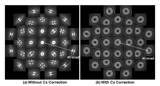
Figs. (a) and (b) show two diffractogram tableaus without Cs correction and with Cs correction, respectively. The diffractogram tableaus are displayed in the following manner. At the center, a diffractogram obtained without tilt of the incident electron is placed, and around the center, the diffractograms obtained by tilting the incident electron beam are placed according to the tilt angles and azimuth angles.
When the incident beam is tilted, the shapes of the diffractograms are distorted depending on the magnitudes and symmetries of the axial (geometrical) aberrations. In Fig. (a), each diffractogram for the tilted electron beam is largely distorted from a perfect circle, which is caused mainly by the third-order spherical aberration. In Fig. (b), the diffractograms taken at the tilted incident beams keep almost circular shape and show small difference between the patterns of the diffractograms, indicating the aberrations being almost corrected.
関連用語から探す
説明に「ディフラクトグラムタブロー」が含まれている用語


