転位ループ
転位ループ
dislocation loop
[目次:結晶等(結晶構造/材料試料)]
転位ループとは、転位線が閉じた輪を形成したものである。転位ループの種類は、せん断転位ループとプリズマティック転位ループの二つに大別される。
せん断転位ループは、せん断応力をかけることにより既存の転位から形成され、材料の変形の原因となる。材料の硬化の理解に重要である。
プリズマティック転位ループは、平板状に集合体した点欠陥 (空孔あるいは格子間原子) の周囲にできる転位であり、それぞれ、不純物の添加や放射線が照射されることにより導入される。半導体の発光特性や原子炉材料の脆性破壊の理解に重要である。
せん断転位ループ
この場合、転位のバーガースベクトルは、転位ループの作る面に平行である。図1に、せん断転位ループが増殖する機構であるフランク・リード機構を示す[1]。滑り面上にあって両端を拘束された転位(図1(a)、(b) に赤線で示すAB)はフランク・リード源と呼ばれる。この転位にせん断応力が掛かると、転位は滑り面上を紙面の上方に張り出し大きくなる。さらに張り出しが大きくなると下方に回り込み、結合することで、転位ループが生成される(図1b)。このとき、フランク・リード源としての転位は初めの状態に戻る。引き続きせん断応力がかかり続けることで、同様の過程が繰り返され、転位ループが次々に生成される(転位の増殖という)。
このせん断転位ループ形成機構によって増殖した転位は、外力が掛かると動いて材料から脱出し、材料は塑性的に変形する(弾性変形から塑性変形への遷移を降伏現象と言う)。また、これらの転位が他の転位と絡み合うと材料が硬くなる(加工硬化)原因となる。
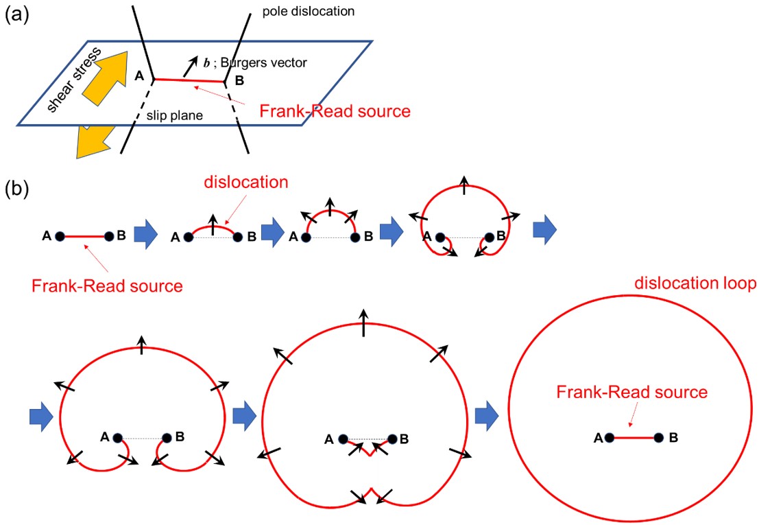
図1 フランク・リード機構によるせん断転位ループの増殖。
(a)滑り面上にあるフランク・リード源の鳥観図。転位のバーガースベクトルは滑り面内にある。転位はA点およびB点で固定されている。
(b)フランクとリードによる転位の増殖機構の模式図。転位線ABにせん断応力が掛かると、転位は上方に拡張し、さらに下方に回り込み、結合して転位ループが作られる。その際、転位線ABは初めの状態に戻る。
プリズマティック転位ループ
この転位ループのバーガースベクトルは、転位ループの作る面 (紙面に垂直な面) に垂直である。図2に、プリズマティック転位ループの空孔型(a) と格子間原子型(b) の模式図を示す。矢印はバーガースベクトルの向きを示す。点線の白丸は原子空孔、赤丸は格子間に注入された原子(格子間原子)である。
プリズマティック転位ループの型 (空孔型あるいは格子間原子型) とその挙動 (形成、成長・縮小、移動、合体、消滅) は、異種元素を注入する半導体の電気・発光特性や、高エネルギー粒子の照射下で使用される原子炉・核融合炉材料における機械特性の劣化過程の解明に重要である [2, 3]。
プリズマティック転位ループの観察例
プリズマティック転位ループの型が空孔型か格子間型かは、明視野あるいは暗視野像に現れる転位ループの回折コントラストを利用して決められる(インサイド―アウトサイド・コントラスト法 [5])。
図3 に、プリズマティック転位ループの像が、励起された反射 g の正負に対してどのように現れるかを示す。転位ループのうち、インサイド・コントラスト(実際の転位より内側に像ができて小さな像になる)の典型例を青矢印で、アウトサイド・コントラスト(実際の転位より外側に像ができて大きな像になる)の典型例を赤矢印で示す。
図 (a) および 図 (b) 中にAでしめす転位ループは同じ転位ループである。転位ループAはg = -1-1 0を励起した場合にアウトサイド・コントラスト(a)を示し、g = 1 1 0を励起した場合ではインサイド・コントラスト(b)を示した。解析の結果、プリズマティック転位ループの型は格子間原子型と決定された [4]。
なお、転位ループBも格子間原子型と決定されたが、Aとは逆のコントラストを示している。その理由は、入射電子線に対する転位の傾きが、転位ループAと逆であるためである。
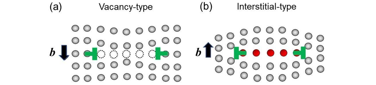
図2 プリズマティック転位ループの模式図。(a) 空孔型と(b) 格子間原子型。矢印は、バーガースベクトルの向きを示す。点線の白丸は原子空孔、赤丸は格子間に挿入された母相または異種原子である。
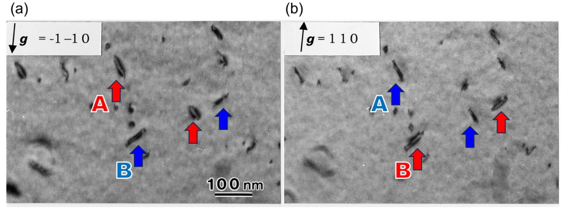
図3 鉄にヘリウムイオン照射することによって形成されたプリズマティック転位ループの回折コントラスト(明視野像)[4]。観察方位は[001] 方向近傍、加速電圧200kV。 (a) および (b) は、符号が互いに逆の反射 g で同一領域を撮影したものである。転位ループA、Bは、励起する反射の符号を逆にすると、アウトサイドコントラストからインサイドコントラストに変わる。このことを使って、これらの転位ループは格子間原子型と決定された。
写真は、島根大学に設置されたイオン加速器結合型 JEM-2010によって撮影された。
(島根大学 荒河 一渡教授 執筆)
References
[1] J.P. Hirth and J. Lothe, Theory of dislocations (2nd ed.), Wiley, New York (1982).
[2] K. Arakawa et al., Science 318, 956-959 (2007).
[3] 荒河一渡, 森博太郎, まてりあ 48号, 第一号, 11-15 (2009), in Japanese.
[4] K. Arakawa et al. J. Appl. Phys. 89, 4752-4757 (2001).
[5] M.L. Jenkins and M.A. Mark, Characterization of radiation damage by transmission electron microscopy (2nd ed.), Institute of Physics Publishing, Bristol (2000).
“Dislocation loop” is a closed loop of a dislocation line. There are two types of the dislocation loops: “shear dislocation loop” and “prismatic dislocation loop”.
The shear dislocation loop is created by applying shear stress to an existing dislocation. This dislocation loop causes deformation of a material, and is important to understand work hardening of materials.
The prismatic dislocation loop is a dislocation produced around a planer cluster of interstitial atoms or vacancies, which are introduced respectively by doping impurities or radiation exposure to a material. The prismatic dislocation loop is important to understand the luminous characteristic of semiconductors and the brittle fracture of reactor materials.
Shear dislocation loop
The Burgers vector of the shear dislocation loop is parallel to the plane where the dislocation loop exists. Fig. 1 shows “Frank-Read mechanism”, which is a mechanism to multiply the shear dislocation loop [1]. A dislocation pinned at both ends A and B on the slip plane (the red line in Fig. 1(a), (b)) is called a Frank-Read source. When shear stress is applied to this dislocation (Frank-Read source), the dislocation expands upward along the slip plane and becomes larger. When the dislocation expands further, it wraps downward and touches itself to form a dislocation loop as shown in Fig. 1(b). The original dislocation returns to its initial state (Frank-Read source). Continued shear stress leads to the repeated generation of dislocation loops (called “multiplication of dislocations”).
Dislocations multiplied by the shear dislocation loop formation mechanism move and escape from the material when an external force is applied. As a result, the material deforms plastically. (transition from elastic to plastic deformation, is called “yield phenomena”) When these dislocations become entangled with other dislocations, they cause to harden materials (work hardening).
Fig. 1. Formation of a shear dislocation loop by the Frank-Read mechanism.
(a) Birds-eye-view of the Frank-Read source on a slip plane. The Burgers vector of dislocation is in the slip plane. The dislocation is pinned at points A and B.
(b) Schematic of dislocation loop creation by the Frank-Read mechanism. When a shear stress is applied to the dislocation line AB, the dislocation expands upward and then, wraps around, and touch itself to create a dislocation loop. The dislocation line AB returns to its initial state.
Prismatic dislocation loop
The Burgers vector of the prismatic dislocation loop is perpendicular to a plane where the dislocation loop exists. Fig. 2 shows a schematic of two types of the prismatic dislocation loop; vacancy type (a) and interstitial type (b). Arrows indicate the directions of the Burgers vectors. White dotted circles show atomic vacancies and red circles show the atoms (interstitials) introduced between the lattices.
The type of the prismatic dislocation loop (vacancy type or interstitial type) and its behaviors (generation, growth/shrinkage, migration, coalescence, annihilation) are important to understand not only the electrical and luminous characteristics of semiconductors doped with hetero-elements, but also deterioration processes of mechanical properties of materials for atomic reactors and nuclear fusion reactors used under irradiation of high-energy particles [2, 3].
Observation example of Prismatic dislocation loop
Whether the type of the prismatic dislocation loop is the vacancy type or the interstitial type is determined by using diffraction contrast of dislocation loops appearing in a bright-field- or dark-field-image (inside-outside contrast method [5]).
Fig. 3 shows an example of how prismatic dislocation loops are seen in TEM images when positive g and negative -g reflections are excited. A typical example of the inside-contrast (the dislocation image is produced inside the real dislocation, resulting in a small image) is indicated by blue arrows, and a typical example of the outside-contrast (the dislocation image is produced outside the real dislocation, resulting in a large image) is indicated by red arrows.
The dislocation loops indicated by A in Fig.3 (a) and (b) are the same dislocation loops. They show outside-contrast when g = -1-1 0 is excited (a), and inside-contrast when g = 1 1 0 is excited (b). The analysis determined the dislocation loop A to be the interstitial type [4].
The dislocation loops B were also determined to be the interstitial type, but showed opposite contrast to A. This is because the inclination of the dislocation loops against the incident electron beam is opposite to A.
Fig. 2. Schematic of the prismatic dislocation loop. (a) Vacancy type and (b) Interstitial type. Arrows indicate the directions of the Burgers vectors. White dotted circles show atomic vacancies and red circles show matrix atoms or hetero-atoms introduced between the lattices.
Fig. 3. Bright-field images (exhibiting diffraction contrast) of prismatic dislocation loops in an iron specimen produced by irradiating helium ions [4], taken near the [001] incidence at an accelerating voltage of 200 kV. Figs (a) and (b) were taken from the same area respectively with opposite reflections g = -1-1 0 and g = 1 1 0. Dislocation loops A and B change their contrast from outside-contrast to inside-contrast when the sign of the exciting reflection is reversed. Utilizing this behavior, these dislocation loops were determined to be the interstitial type.
These images were taken with a JEOL JEM-2010 combined with an ion-accelerator, installed at Shimane University.
(By Professor Kazuto Arakawa, Shimane University)
References
[1] J. P. Hirth and J. Lothe, Theory of dislocations (2nd ed.), Wiley, New York (1982).
[2] K. Arakawa et al., Science 318, 956-959 (2007).
[3] K. Arakawa and H. Mori, Material (Japanese) 48, 1, 11-15 (2009), in Japanese.
[4] K. Arakawa et al. J. Appl. Phys. 89, 4752-4757 (2001).
[5] M. L. Jenkins and M.A. Mark, Characterization of radiation damage by transmission electron microscopy (2nd ed.), Institute of Physics Publishing, Bristol (2000).
関連用語から探す
説明に「転位ループ」が含まれている用語


