電子らせん波
電子らせん波
Vortex electron wave
[目次:理論(電子の散乱/回折/結像)]
らせん状の波面(等位相面)をもって空間を伝搬する電子波。波面がらせん状であることから、中心軸のまわりを等位相面に沿って一周まわると、波面は軸方向に1波長の整数ℓ倍変位するものだけが許される。この変位は、波長λの整数ℓ倍すなわちℓλと表せる。この整数ℓはトポロジカル数、トポロジカル量子数、トポロジカルチャージ等と呼ばれ、らせん波を特徴づけるパラメーターである。回転を表す物理量は角運動量であり、中心軸周りの位相の回転は(軌道)角運動量に対応させることができるので、らせん波は軌道角運動量をもつ波と言える。らせん波の軌道角運動量は、トポロジカル数ℓにh /2πを掛けた値として与えられる。
2010年に内田と外村は、厚さがらせん状に変わるグラファイトに電子平面波を入射し、透過した電子波とグラファイトを透過しない参照波を干渉させ、その位相変化からグラファイトを透過した電子波の波面がらせん状に成っていることを実験的に示した。その後、電子らせん波は、らせん状に成型した位相板のほかに、フォーク型回折格子(図1a)、スパイラルゾーンプレート(図1b)などによって生成できることが分かっている。
光のらせん波は1992年に発見されており、その角運動量の授受を利用して回転操作を行う光ピンセットに応用されている。電子らせん波では、電子が電荷をもつことから、その磁気モーメントと磁性体との相互作用を利用した磁気イメージングが期待されている。
図2の上図は、らせん波の等位相面を示す。ℓ=0は平面波をあらわす。等位相面に沿って中心軸のまわりを1回転すると元の位置に戻る。ℓ=1のらせん波では、等位相面に沿って中心軸のまわりを1回転すると軸方向に1波長進むことを橙色の面で示す。ℓ=‐1のらせん波では、等位相面に沿って中心軸のまわりを1回転すると逆方向に1波長進む。ℓ=2のらせん波では、等位相面に沿って中心軸のまわりを1回転すると軸方向に2波長進むことを橙色の面で示す。緑色の面は、橙色の面が2波長進むことを見やすくするために入れた補助面である。ℓ=3のらせん波では、等位相面に沿って中心軸のまわりを1回転すると軸方向に3波長進むことを橙色の面で示す。紫色と緑色の面は、橙色の面が3波長進むことを見やすくするために入れた補助面である。
図2の下図は、らせん波の進行方向と垂直な断面での強度分布である。らせん波では中心軸上の位相が定まらない(位相特異点である)ために、中心軸上では有限の振幅をもつことができない。その結果、らせん波のビームの断面を見ると中心軸上の強度はゼロ(暗点)になる。角運動量を持たないℓ=0(平面波)のときは、中心の強度が最も大きい。ℓ≠0のらせん波では、中心での強度は0になっている。ℓが大きくなるにつれて強度のリングの半径が大きくなっている。
図3は、フォーク型回折格子に平行な電子線を照射して得た回折図形である。透過波の両側にある回折波の強度がリング状になっており中心に暗点が見られることから(図2の下図を参照)、検出された回折波が電子らせん波であることがわかる。
図1 電子らせん波を生成するために平面電子波を通過させるプラチナ製マスク⇒図
(a) フォーク型回折格子 (b) スパイラルゾーンプレート
図2 らせん波の等位相面の模式図(上)とらせん波の動径強度分布(下)⇒図
図3 電子らせん波の検証⇒図
フォーク型回折格子に、平行な電子線を透過させて得た回折図形。回折波の強度がリング状で中心に暗点が見られることから、検出された電子波がらせん波であることが検証された。
A vortex electron wave is an electron wave that propagates in a space with a spiral wavefront (or a spiral equiphase plane). Since the wavefront of the electron wave is of a spiral shape, only waves which create an advance of ℓ(ℓ= integer) times the wavelength in the axial direction is allowed for one turn about the central axis along the equiphase plane. Here, ℓ is called topological number, topological quantum number or topological charge, and is a parameter characterizing the vortex wave. Since the physical quantity characterizing a rotation is the angular momentum, a phase rotation with respect to the central axis can be considered to have an (orbital) angular momentum. This means that the vortex electron wave is a wave carrying an orbital angular momentum. The orbital angular momentum is given by ℓ×h/2π, where h is the Planck constant.
In 2010, Uchida and Tonomura experimentally demonstrated the formation of a vortex electron wave using a spiral-shaped phase plate. In their experiment, a plane electron wave was incident onto a graphite with a spiral-shaped thickness change. The transmitted electron wave was interfered with a reference wave which does not pass through the graphite. Then, they confirmed that the transmitted wave has a spiral-shaped wave front or is a vortex wave. Afterwards it was found that the vortex electron wave can be formed also using a fork-shaped grating (Fig.1a), a spiral zone plate (Fig.1b), etc.
A vortex light wave was discovered in 1992. It has been used for rotation operation of light tweezers by transferring the orbital angular momentum of the wave. For the vortex electron wave, magnetic imaging is expected by utilizing interactions between magnetic material and magnetic moment of the vortex electron wave originating from the spiral rotation of electrons.
The upper figures of Fig.2 show the equi-phase planes of vortex electron waves. The wave with ℓ= 0 expresses a plane wave. A point on the orange plane comes back to the same point for one turn about the central axis. The vortex wave of ℓ= 1 creates an advance of one-wave length in the axial direction for one turn on the equi-phase plane about the central axis, which is illustrated by orange planes. The vortex wave of ℓ= -1 creates an advance of one-wave length in the opposite direction for one turn on the equi-phase plane about the central axis. The vortex wave of ℓ= 2 creates an advance of two-wave length in the axial direction for one turn on the equi-phase plane. Green planes in Fig.2 are drawn for easily recognizing the two-wave length progress of the orange planes. The vortex wave of ℓ= 3 creates an advance of three-wave length for one turn on the equi-phase plane. Purple and green planes are drawn for easily finding the three-wave length progress of the orange planes.
The lower figures of Fig.2 show the intensity distribution of the vortex electron wave for the vertical cross section of the wave. Since the vortex electron wave does not have a fixed phase at the central axis (a phase singular point), the vortex wave is unable to have a finite amplitude on the central axis. As a result, the intensity on the central axis must be zero (dark spot) for the vortex waves (ℓ≠ 0). For ℓ= 0 (plane wave) the wave does not have any angular momentum and any singular point, and the intensity on the central axis takes a maximum value. The larger ℓ is, the larger the radius of the intensity ring becomes.
In Fig.3, a diffraction pattern taken by illuminating a parallel electron beam onto a fork-shaped grating is shown. The intensities of the diffracted waves at the both sides of the transmitted wave are ring-shaped and have dark spots at the respective centers (see the lower figures of Fig.2). This result confirms that the detected electron wave is a vortex electron wave.
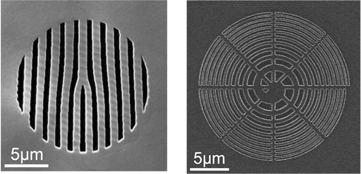
Fig.1 Platinum mask to form a vortex electron wave by passing a plane electron wave through it.
(a) Fork-shaped grating mask and (b) Spiral zone plate mask.
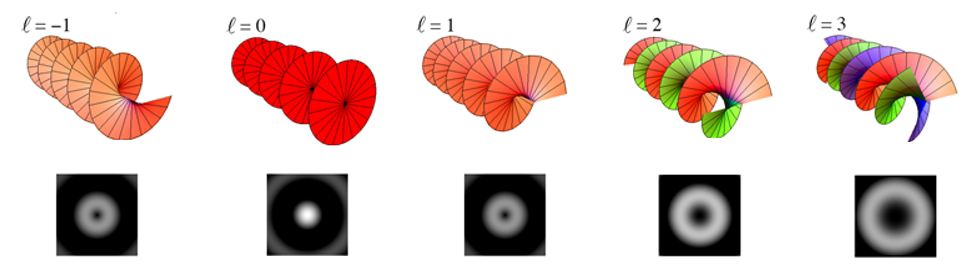
Fig. 2 Schematics of equi-phase plane of the vortex wave (top) and radial intensity distribution of the wave (bottom).
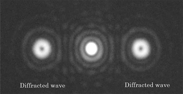
Fig. 3 Examination of the vortex electron wave.
Diffraction pattern taken by passing a parallel electron beam through a fork-shaped grating mask. The diffracted waves at the both sides of the transmitted wave have ring-shaped intensity distributions and dark spots at the respective centers. This confirms that the detected electron wave is a vortex electron wave.
説明に「電子らせん波」が含まれている用語


