ローレンツ電子顕微鏡法
ローレンツ電子顕微鏡法
Lorentz electron microscopy
[目次:理論(電子の散乱/回折/結像)]
透過電子顕微鏡を用いて強磁性体試料の磁区構造を観察する手法。強磁性体に入射した電子は試料の磁化の方向に垂直な力(ローレンツ力)を受けて進行方向を変える(偏向する)(図1)。入射電子線は試料の隣り合う磁区で曲げられる向きが逆になるので、これを利用して試料の磁区構造を調べることができる。広く用いられる方法としてはフレネル(Fresnel)法とフーコー(Foucault)法がある。
Fresnel法では、図2に示すように、磁化の方向が180度異なって隣り合う磁区で電子線の受ける偏向方向が逆になる。左側の磁壁部分では電子線は磁壁を挟んで近づくように曲げられ電子線の強度が増す。右側の磁壁部分では電子線は磁壁を挟んで遠ざかるように曲げられ強度は減る(図2(a)-(c))。レンズの焦点を試料の下面に合わせた場合は電子線の重なった(開いた)部分の幅は狭く観察は難しいが、焦点をずらすと電子線の重なった(開いた)部分は拡大され、磁区境界(磁壁)は明るい(暗い)線として明瞭に観察される(図2(d)-(f))。Fresnel法は焦点外しを用いているのでdefocus法とも言われる。
Foucault法では、図3に示すように、磁化の方向が180度異なって隣り合う磁区からの回折斑点が後焦点面で少しずれた位置にできるので、その一方を選んで結像する。選ばれた回折斑点に対応する磁区は明るく、選ばれなかった回折斑点に対応する磁区は暗く見える。Foucault法では焦点外しを必要としないのでinfocus法とも言われる。
上記の二つの方法の他に、電子線ホログラフィーや微分位相コントラスト法をもある。
通常の透過電子顕微鏡では、試料は対物レンズの強い磁場中に置かれ(最大2T程度)、入射電子線(磁場)の方向に磁化され、試料全体が単一磁区になってしまう。そのため磁区構造の観察には対物レンズをOFFにして、対物レンズ以降の他の結像系レンズ(対物ミニレンズ)を使用し、試料に磁場がかからない条件下で観察を行う必要がある。試料位置にほとんど磁場がかからない専用の対物レンズを搭載した電子顕微鏡も開発されている。
図4, 5にNd2Fe14B永久磁石の磁区構造を異なる方向から観察した結果を示す。
図4(a),(b),(c)はFresnel法による観察結果を示す。図4では、試料の磁化は概ね電子線入射方向と平行に(試料面に対して垂直)なっているが、完全には電子線の方向と一致していない(平行にはなっていない)。そのため、入射電子線に対して垂直な磁化の成分が電子線を偏向させ、メイズ(迷路)状の磁壁に明暗の差(コントラスト)を与える。図(a)はinfocus、図(b)はunderfocus、図(c)はoverfocusの場合である。図(d), (e)は、それぞれ図(b), (c)中に示す矩形領域の拡大像である。図中、白黒の矢尻でしめす明線、暗線が磁壁に相当する。in-focusの像では磁壁は幅が狭すぎて見えないが、focus をずらした図(d)、(e)では磁壁が明瞭に見られる。Focusずらしの正負により磁壁の明暗が反転していることが分かる。
図5(a),(b),(c)はFoucault法による観察結果を示す。ここでは試料の磁化は電子線に対して垂直(試料面に対して平行)で、隣り合う磁区では磁化が逆向きになっている。通常の明視野観察条件(図(a))では磁区のコントラストは観察されないが、絞りの位置を変えて、どちらか一方の磁化をもつ磁区からの回折斑点を選ぶと、ストライプ(縞)状の磁区が明瞭に観察される(図(b))。絞りの位置を変え、もう一方の回折斑点を選択すると、隣り合う磁区の明暗が反転する(図(c))。

図1. 磁化Bを持つ磁性材料による電子線の偏向の模式図
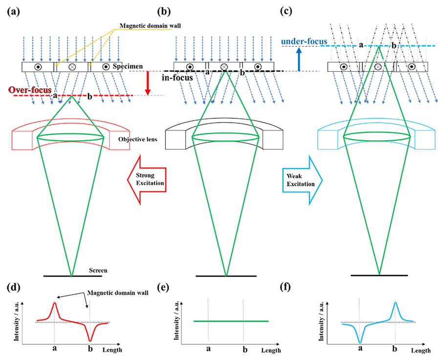
図2. Fresnel法の模式図。
結像系のレンズ強度を増減させることで、取得する像の位置が変化する。(a)overfocus:試料の底面より下方の面に焦点合わせをした場合、(b) infocus:試料の底面に焦点合わせをした場合、(c) underfocus:試料の底面より上方の面に焦点合わせをした場合。(d) overfocus, (e)infocus, (f) underfocusの場合における磁壁の像の強度プロファイルを示す。Infocus (e)では磁壁の部分で強度プロファイルに変化は生じないが、図中 “a” で示す磁壁位置に注目すると、overfocus (d)では、磁壁は明るく(強度が増加)見え, underfocus (f)では暗らく(強度が減少)見える。underfocus、overfocusでの強度プロファイルの反転を利用すると試料中での磁化の向きを決定できる。
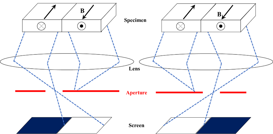
図3. Foucault法の模式図。
試料中の磁化の向きの違いにより、電子線が受ける偏向の向きが逆になり、対物レンズ(または対物ミニレンズ)の後焦点面で異なる位置に回折斑点が生じる。一方の回折斑点のみを絞りで選択すると、選んだ回折点に対応する磁区は明るくなり、絞りで除かれた回折点に対応する磁区は暗くなって、磁区は可視化される。
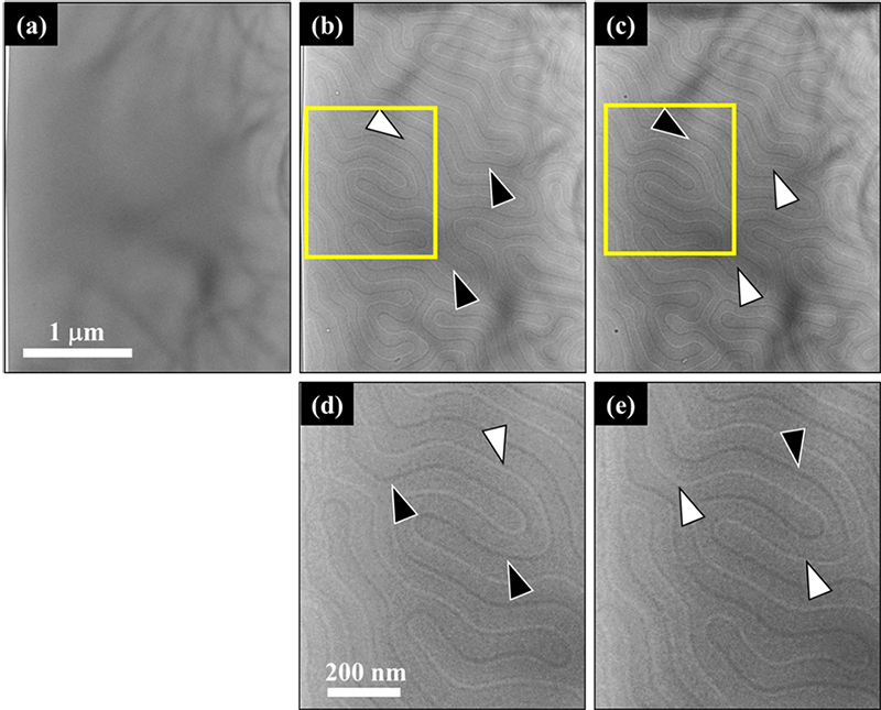
図4. Fresnel法によるNd2Fe14B永久磁石の磁区の観察。
(a)infocus, (b)underfocus, (c)overfocus。図(d), (e)はそれぞれ図(b), (c)中に示す黄矩形領域の拡大像。図中に白黒の矢尻で示す明線、暗線が磁壁に対応する。
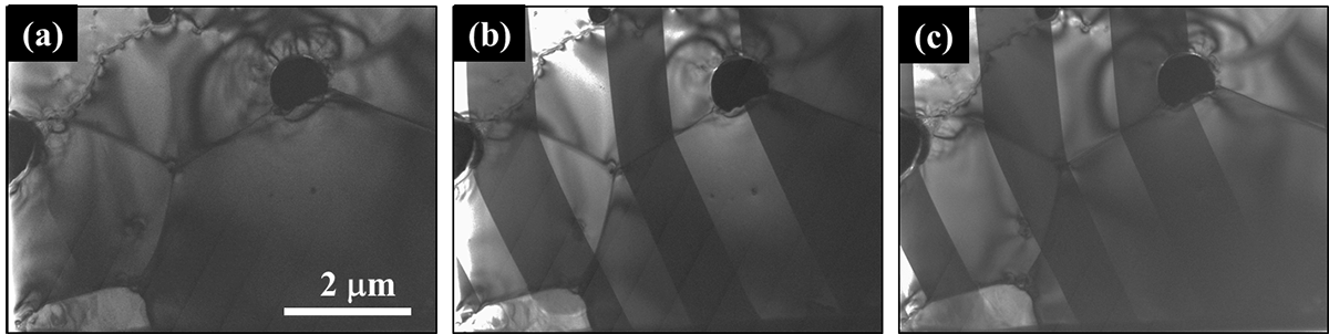
図5. Foucault法によるNd2Fe14B永久磁石の磁区の観察。
(a) 両方の磁区からの回折斑点を選択した場合。磁区は可視化されない。
(b),(c) 一方の磁区からの回折斑点だけを選択した場合。一方の磁区は強度をもち、他方の磁区は強度を失い、磁区構造が可視化される。
A method to observe magnetic domain structures of a ferromagnetic material using a transmission electron microscope (TEM). Electrons incident onto a ferromagnetic material undergo a force perpendicular to the magnetization direction of the ferromagnetic specimen (Lorentz force), thus their traveling direction changes, as shown in Fig. 1 (electrons are deflected). Since electrons passing through the adjacent domains of the specimen are deflected in opposite directions, this phenomenon enables us to study magnetic domain structures of the specimen. “Lorentz electron microscopy” has two modes which are widely used: Fresnel mode and Foucault mode.
In the Fresnel mode, as shown in Fig. 2, in the adjacent magnetic domains with magnetization direction being different by 180° to each other, the incident electron beams are deflected in the opposite directions. At the left magnetic domain wall, the electron beams passing through the adjacent magnetic domains are deflected closer (overlap) to each other to increase the intensity of the electron beams (Fig. 2(a) to (c)). To the contrary, at the right domain wall, the electron beams passing through the adjacent domains are deflected away (open) to each other to decrease the intensity of the electron beams (Fig. 2(a) to (c)).
Since the overlapped (open) area of the electron-beams is narrow at the bottom surface of the specimen, the magnetic domain wall is difficult to observe when the lens is focused on the bottom surface. When the focus is displaced (defocus), the overlapped (open) area is enlarged and the magnetic domain wall is clearly observed as light (dark) lines (Fig. 2(d) to (f)). The Fresnel mode is also called “defocus method” because it uses the defocus technique.
In the Foucault mode, as shown in Fig. 3, the diffraction spots from the adjacent magnetic domains with magnetization direction being different by 180° to each other, are formed at slightly different positions on the back focal plane, and one of these spots is selected for imaging. The domain that corresponds to the selected diffraction spot appears light whereas the domain corresponding to the unselected diffraction spot appears dark. Since the Foucault mode does not need the defocus technique, this mode is also called “infocus method”.
In addition to these two modes, “electron holography” and “differential phase contrast (DPC)” technique are used.
In a usual TEM, since the specimen is placed in a strong magnetic-filed (maximum~2T) of the objective lens, the specimen is magnetized in the direction of the incident electron beam (magnetic field) and the entire specimen becomes a single magnetic domain. Thus, to observe the magnetic domain structure, it is necessary to turn off the objective lens and to use another lens in the imaging lens system (objective mini lens) under a condition where the specimen is not subjected to a magnetic field.
It is noted that TEMs equipped with a special objective lens applying nearly no magnetic field to the specimen position have also been developed.
Fig. 4 and 5 show usual and Lorentz TEM images of the magnetic domain structure of a permanent magnet of Nd2Fe14B, observed from different directions.
Fig. 4(a), (b) and (c) show Lorentz TEM images taken by the Fresnel mode. In Fig. 4, the magnetization direction of the specimen is approximately parallel to the incident electron beam (perpendicular to the specimen plane), but not completely parallel to the electron-beam direction. As a result, the magnetization components perpendicular to the incident electron beam deflect the beam and provide light and dark magnetic domain walls in a maze-like magnetic pattern. Fig. 4(a), (b) and (c) show respectively the case of infocus, underfocus and overfocus.
Fig. 4(d) and (e) show the enlarged images of the rectangular area of Fig. 4(b) and (c), respectively. The light line and dark line indicated by white and black arrowheads correspond to the magnetic domain wall. In the infocus image (a), the wall cannot be observed because the width of the wall image is too narrow, but in the defocus images (d) and (e), the magnetic domain walls are clearly observed. It is noticed that light and dark images of the magnetic domain wall are reversed by the positive or negative defocus (overfocus or underfocus).
Fig. 5(a) is a usual TEM image and Fig. 5(b) and (c) are Lorentz TEM images taken by the Foucault mode. In this case, the magnetization direction of the specimen is perpendicular to the incidence electron beam (parallel to the specimen plane), and the magnetization directions of the adjacent domains are opposite. In the usual bright-field imaging condition (a), no contrast is observed between the magnetic domains. However, when the aperture position is changed to select one of diffraction spots produced by either of magnetic domains, stripe-shaped magnetic domains are clearly observed (b). When the aperture position is changed to select the other one of diffraction spots, the light and dark images of the adjacent domains are reversed (c).
Fig. 1. Schematic of the deflection of the electron beam due to magnetization B of a magnetic material.
Fig. 2: Schematic of the Fresnel mode.
By increasing or decreasing the lens intensity of the imaging system, the position of the acquired image is changed. (a) overfocus: the lens is adjusted to focus on a plane lower than the bottom surface of the specimen. (b) infocus: the lens is focused on the bottom surface of the specimen, and (c) underfocus: the lens is focused on a plane upper than the bottom surface of the specimen.
The intensity profiles of the magnetic domain wall images in the cases of overfocus, infocus, and underfocus are respectively shown in (d), (e), and (f). In infocus (e), no change in the intensity profile occurs at the magnetic domain walls, but in overfocus (d) and underfocus (f), the magnetic domain walls appear as light (with intensity increase) or dark (with intensity decrease) for the magnetic domain wall “a”. The reversal of image profiles between the underfocus and overfocus cases can be used to determine the direction of magnetization of the specimen.
Fig. 3. Schematic of the Foucault mode.
The directions of the deflection of the electron beams are reversed due to the inversion of magnetization directions of the specimen. Diffraction spots are produced at the different positions on the back focal plane of the objective lens (or the objective mini lens). When selecting one diffraction spot by the aperture, the domain that corresponds to the selected diffraction spot appears light whereas the domain corresponding to the diffraction spot unselected by the aperture becomes dark, which makes it possible to visualize the domains.
Fig. 4. TEM images of a permanent magnet of Nd2Fe14B, taken by the Fresnel mode at (a) infocus, (b) underfocus, (c) overfocus. (d) and (e) are the enlarged images that correspond to the rectangular area of (b) and (c) respectively. Magnetic domain walls are observed as light- and dark-curved lines, indicated by white and black arrowheads.
Fig. 5. TEM images of a permanent magnet of Nd2Fe14B, taken by the Foucault mode.
(a) Selecting two diffraction spots produced by both magnetic domains in a usual way. The magnetic domains are not visualized.
(b) and (c) Selecting only one diffraction spot produced by either of magnetic domains. One type of the magnetic domain is seen light whereas the other magnetic domain loses intensity. The magnetic domain structure is visualized.
関連用語から探す
説明に「ローレンツ電子顕微鏡法」が含まれている用語


