マイクロ電子回折法
マイクロ電子回折法
micro electron diffraction method, Micro ED
[目次:理論(電子の散乱/回折/結像)]
入射電子線に対して試料を傾斜しながら動力学的効果を軽減させて回折パターンを取得し、運動学理論(フーリエ変換)を適用して結晶構造を解析する方法。
試料上の数µm程度の領域に電子線を照射し、試料を傾斜(0.1~1 deg/s で 30°~60°程度)させながら、回折パターンを動画もしくは一連のフレーム画像として取得する。このようにして得られた回折強度にX線構造解析法の手法(具体的には直接法など)を適用して、結晶の構造解析を行う。
通常、電子回折では、同時反射の効果(ある反射が、同時に強く励起された他の反射を経由して、強められる効果(動力学効果の一つ))があるので、動力学効果を考慮せず、運動学理論(フーリエ変換)に基づくX線構造解析の手法を適用することができない。しかし、試料を傾斜させながら回折パターンを取得する。図1に、回折図形の実例を示す。それらのパターンを足し合わせると回折強度が平均化され、同時反射の効果が弱められ、運動学理論から期待される回折強度に近づく。一つの試料から傾斜操作で取得できる角度範囲は限られるので、いろいろな方位を向いた試料に対して傾斜操作を行って得られた回折パターンを組み合わせて、広い角度範囲をカバーしたデータセットを取得する。このデータにX線構造解析の手法、直接法を適用して構造解析を行う。 ※1.
マイクロ電子回折法の特徴は以下の通りである。
電子に対する結晶の散乱断面積はX線に対する散乱断面積に比べて104 倍程大きいため、サイズ1µm以下の微結晶から十分強い回折強度が得られる。そのため、微小結晶しか得られない有機および無機化合物の構造解析に有効である。X線構造解析の場合、数10µm程度の大きな結晶が必要である(放射光施設を使用すると数µm程度の大きさの結晶まで可能)。なお、電子回折の場合の注意点として、電子線による試料損傷が問題となることがあり、液体窒素による試料の冷却や電子線のドーズ量の低減が必要である。
※1. 註釈
荷電粒子である電子は、結晶内原子の原子核と電子で作る電位(ポテンシャル)によって散乱される。電磁波であるX線は、結晶内原子の電子密度に比例して散乱 (Thomson散乱という) される。原子核は、電子に比べてはるかに重いのでX線によって振動しないため、X線の散乱には寄与しない。したがって、電子回折による結晶構造解析からは、結晶内原子のポテンシャル分布が求まり、X線回折の場合には電子の密度分布が求まる。両者は変換公式によって関係づけられており、一方が求まれば他方も求まる。

図1.L-ヒスチジン微結晶の試料を傾斜しながら逐次撮影した電子回折パターン。
傾斜角度範囲:–16° ~ +15° 傾斜スピード:0.1°/s. 電子線照射量:0.06 e-/Å2/s. 加速電圧 200 kV.
各フレームに示す角度は各回折パターン取得の開始時の傾斜角度である。
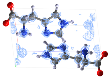
図2.構造が既知であるL-ヒスチジンにマイクロ電子回折法を適用し、構造解析から得られた等電位面(ポテンシャルマップ)をメッシュパターンで示した。
中性子回折法により得られている分子モデルを重ねて示す。マイクロ電子回折法による結果は既知の構造をよく再現している。
(各元素と色表示の対応は次の通り: C-灰; N-青; O-赤; H-白)
(Reconstruction model: Courtesy of Dr. Yusuke Nishiyama (JEOL RESONANCE Inc.))
The micro electron diffraction method is a method to determine crystal structures using electron diffraction patterns with the help of the kinematical diffraction theory (Fourier transform), where the diffraction patterns are acquired while continuously tilting small crystalline specimens against the incident electron beam to reduce the dynamical diffraction effect.
A specimen size to be used is a few µm in diameter, and is tilted up to 30 to 60° at a step of 0.1 to 1 deg/sec. Several series of diffraction patterns are taken as movie or frame images. Then, the crystal structures are determined by applying a method broadly used in X-ray crystal structure analysis (the direct method) to the present diffraction data obtained.
In ordinary electron diffraction, the simultaneous reflection effect (one of dynamical diffraction effects) arises, that is a certain reflection is enhanced via the other reflections simultaneously excited. Thus, X-ray crystallography method based on the kinematical theory (Fourier transform), which does not take account of the dynamical diffraction effect, cannot be applied to electron diffraction. However, when diffraction patterns are acquired while tilting a specimen and summing up the intensities of each diffraction pattern, the diffraction intensity is averaged and the simultaneous reflection effect decreases, and then the obtained diffraction intensities approach to those expected from the kinematical theory. Fig. 1 shows an example of a series of diffraction patterns. Since the angler range and the directions of tilting for one specimen are limited, several series of tilt operations are performed for the specimens with different crystal orientations.Then, the acquired diffraction patterns are combined to form a dataset covering a wide angler range and different orientations. For this data set, the direct method in X-ray crystallography is applied to determine the crystal structure. *1
The features of Micro ED are as follows.
The scattering cross section of a crystal for electrons is 104 times larger than that for X-rays. Thus, sufficiently-high electron diffraction intensities are obtained even from a micro-crystal of 1 µm or less in size. Therefore, Micro ED is effective for structural analysis of organic- and inorganic-compounds from which only micro-crystals are prepared. In the case of X-ray structure analysis, a large-crystal of several 10 µm in size is needed. (It is possible to use a crystal with a size down to several µm when a synchrotron radiation light source is used.) For electron diffraction, it should be noted that a radiation damage of a specimen due to electron-beam irradiation can arise. To avoid this problem, it is required to cool the specimen with liquid nitrogen and to decrease the electron dose.
*1. Note
An electron, a charged particle, is scattered by the electrostatic potential formed by both the nucleus and electrons of the atoms in a crystal. An X-ray, an electromagnetic wave, is scattered by the electrons of the atoms in a crystal (Thomson scattering). It is noted that an atomic nucleus does not contribute to the X-ray scattering because the nucleus is too heavy to be vibrated by X-rays.
Thus, structural analysis using electron diffraction determines the electrostatic potential distribution in a crystal, whereas structural analysis by X-ray diffraction determines the electron density distribution in a crystal. It is known to exist a conversion formula between the electrostatic potential distribution and the electron density distribution in a crystal. Thus, if one is found, the other is found by the conversion.
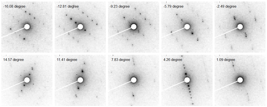
Fig. 1 Tilt-series of electron diffraction patterns obtained from an L-histidine micro-crystal.
Angular tilt range: –16° to +15°. Tilt speed: 0.1°/s. Electron dose: 0.06 e-/Å2/s. Accelerating voltage: 200 kV.
The angles indicated in each frame are the tilt angles at the start of acquiring each diffraction pattern.

Fig. 2 For L-histidine with a known molecular structure, the Micro ED method was applied.
The grid (mesh) pattern shows the equi electrostatic potential planes (potential map) obtained by the method. A molecular model obtained by neutron diffraction is overlaid on the grid pattern. The reconstruction pattern obtained by the Micro ED method is in good agreement with the already reported structural model. (In the model, the respective elements are indicated by the different colors. C: gray, N: blue, O: red, H: white)
(Reconstruction model: Courtesy of Dr. Yusuke Nishiyama (JEOL RESONANCE Inc.))
関連用語から探す
説明に「マイクロ電子回折法」が含まれている用語


