転位のバーガースベクトルの決定(CBED法による)
転位のバーガースベクトルの決定(CBED法による)
Burgers vector determination of a dislocation using CBED
[目次:理論(電子の散乱/回折/結像)]
CBED 法を用いると転位のバーガースベクトル b を一意に決定することができる。
TEM像を使う方法では、バーガースベクトルの決定に g ∙ b = 0 の情報しか使えないが、CBED法ではこれに加えて g ∙ b = n ≠ 0 の情報まで使えるので、バーガースベクトルについての予備情報 (可能な候補)が必要でなく、一義的にバーガースベクトルが決定できる [1, 2]。
図1に、バーガースベクトル決定のためのdefocus CBED図形の撮影方法を模式的に示す。入射収束ビームの焦点を試料から上方にずらして (defocusして)、転位の歪みが及んでいる範囲全体を照射してCBED図形を撮影する (Defocus CBED法)。
反射 g の回折線の主極大は、転位線と交わるところで転位の歪によって反射が起こる条件(角度)が変わり、図1のように回折線が曲がる (ずれる)。計算機シミュレーションから、g ∙ b = n になる反射 g のdefocus CBED図形には、n 個の節を持つ反射線が現れることが知られている[2]。また、n の符号は反射線の曲がり (ずれ)の向きから判別できる(後述)。
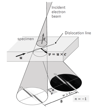
図1 転位を含む領域からのdefocus CBED 法の模式図。
ここで g は反射の逆格子ベクトル、u は転位線のベクトル(向きの取り方は任意)、c は試料上の照射領域の中心から入射ビームの焦点に向かうベクトル、v は v = u × c により定義されるベクトルである。w は、励起誤差 s に消衰距離 ξg を掛けた無次元量 w = sξg であり、w > 0の向きは反射 g から透過波に向かう方向となる。
次に、3個の異なる反射 g について節の数 n を調べる。このとき3個の g として一次独立な反射、すなわち同一平面内(同一ラウエ帯)にない反射が必要になる。バーガースベクトルを b = [uvw]として g ∙ b = n の3元連立1次方程式を解くことで b が曖昧さなく得られる。
n の符号は以下のようにして決める。バーガースベクトルの取り方はFS/RH conventionに従うものとする[3]。転位線の向きの取り方は任意なので、図1(a)の矢印 u の向きにとることにする。試料上での照射領域の中心から入射ビームの焦点に向かうベクトルを c とする。ここで v = u × c というベクトルを定義する。
v の原点は転位線の上にとり、転位線の v > 0 の側に着目する。v > 0 の側で回折線の曲がり方(直線からずれてゆく方向)が(図1のように)反射ベクトル g の向きと同じなら n は負とし、曲がりが g と反対向きなら n は正とする。図1では n = −1 となる。
図2 に、Si の転位による歪み領域をカバーするように電子線を照射して撮影したdefocusCBED 図形の例を示す。転位のバーガースベクトルを b = [uvw] として、3 個の反射、例えば 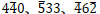 反射について g ∙ b = n の連立方程式をつくると
−5u + 3v + 3w = −4
−4u + 6v − 2w = −1
となり、これを解くと曖昧さなく b = ![反射 [101]/2](./glossary_file/file/burgers_vector_03.png) が得られる。
が得られる。
もう一つの反射  についても、得られた b で g ∙ b を計算すると g ∙ b = 6 となり、CBED 図形から読み取れる n の値 n = + 6 と一致することがわかる。
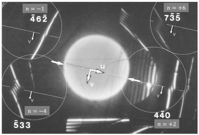
図2 Si の転位から得たdefocus CBED 図形。
各回折ディスクのディスクを白い点線の円で、各反射に現れる転位線の位置を白い点線で示した。また、節の数と回折線の曲がり(ずれ)の向きとから決まる n の値を付記した。 反射と
反射と 反射では、v > 0 の側で回折線の曲がる方向が g ベクトルの向きと反対であり n の符号は正である。
一方、 反射および
反射および 反射では、v > 0 の側で回折線の曲がる方向が g ベクトルの向きと同じであり n の符号は負である。
(東北大学教授 津田健治 執筆)
References
[1] D. Cherns, A.R. Preston, Proc. of the 11th Int. Congr. on Electron Microsc., Japanese Society of Electron Microsc., Kyoto, 1986, p. 721-722.
[2] M. Tanaka, M. Terauchi and T. Kaneyama, J Electron Microsc. 40, 211-220 (1991).
[3] J.P. Hirth and J. Lothe, Theory of dislocations (2nd ed.), Wiley, New York (1982).
The Burgers vector b of a dislocation can be unambiguously determined when convergent-beam electron diffraction (CBED) is applied.
The traditional TEM imaging method uses only the information g ∙ b = 0 to determine the Burgers vector, but the CBED method uses also the information g ∙ b = n ≠ 0 . As a result, the Burgers vector can uniquely be determined without any preliminary information (possible candidates) about the Burgers vector [1, 2].
Fig. 1 illustrates the method to acquire a defocus CBED pattern to determine the Burgers vector. By slightly defocusing the incident convergent beam (shifting the focal point a little upper from a specimen), the convergent beam is illuminated over the whole strained area due to the dislocation. This is called the defocus CBED method. When the principal maximum line of a reflection g intersects with the dislocation line, the reflection line bends or shifts around the intersecting point, as shown in Fig. 1. This is caused by the change of the reflection condition (the diffraction angle) due to the lattice strain by the dislocation.
By computer simulations, it is known that the reflection line exhibits n nodes in the reflection g of a defocus CBED pattern when g ∙ b = n [2]. The sign of n can be determined by the direction of the bend (shift) of the reflection line (described later).
Fig. 1. Schematic of the defocus CBED method, which takes diffraction patterns from the whole strained area due to a dislocation.
Here, g is the reflection vector, u is the vector of the dislocation line, c is the vector which points from the center of the illuminated specimen area to the focus position of the incident beam, the vector v is defined by the equation v = u × c, and w is the dimension-less quantity w = sξg , where s is the excitation error and ξg is the extinction distance.The direction of w > 0 is from the reflection g to the transmitted wave.
Next, count the number of nodes n for three reflections g, where these three reflections have to be linearly independent, that is, they are not in the same plane (same Laue zone). Let the Burgers vector be b = [uvw], and b is unambiguously obtained by solving the ternary linear equation g ∙ b = n.
The sign of is determined by the following way. The direction of the Burgers vector is defined by the FS/RH convention [3]. Since the direction of the dislocation line is arbitrary, the direction is taken in the direction of the arrow u as shown in Fig. 1(a). Let c be the vector from the center of the illuminated area on the specimen to the focus of the incident beam. Here, the vector v is defined as v = u × c. The origin of v is taken on the dislocation line, and we look the side v > 0 across the dislocation line. n is negative if the bend of the diffraction line (the direction of deviation from the straight line) on the side v > 0 is the same as the direction of the reflection vector g (as seen in Fig. 1).
n is positive if the bend is in the opposite direction of g. In Fig. 1, a case of n = −1 is shown.
Fig. 2 shows a defocus CBED pattern taken by illuminating an electron beam to cover the strained area caused by the dislocation of Si.
Let the Burgers vector of the dislocation be b = [uvw], and we make the ternary linear equation g ∙ b = n for three reflections g , for example,  reflections. Then, we obtain the following equations,
−5u + 3v + 3w = −4
−4u + 6v − 2w = −1.
By solving these equations, b = is unambiguously obtained.
For the other reflection , if we calculate g ∙ b using the obtained b, we find that g ∙ b = 6, which is consistent with the value of n read from the CBED pattern, n = +6.
Fig. 2. Defocus CBED pattern taken from the dislocation of Si.
Each diffraction disk is indicated by a white dotted circle, and the dislocation line appearing in each reflection is indicated by a white dot line. Each value of n, determined by the number of nodes and the bending (shift) direction of the reflection line is written.
For and reflections, the bending direction of the diffraction (reflection) line at the side of v > 0 is opposite to the direction of the vector g, then the sign of n is positive. On the other hand, for and reflections, the bending direction of the diffraction line at the side of v > 0 is the same as the direction of the vector g, then the sign of n is negative.
(By Professor Kenji Tsuda, Tohoku University)
References
[1] D. Cherns, A.R. Preston, Proc. of the 11th Int. Congr. on Electron Microsc., Japanese Society of Electron Microsc., Kyoto, 1986, p. 721-722.
[2] M. Tanaka, M. Terauchi and T. Kaneyama, J Electron Microsc. 40, 211-220 (1991).
[3] J.P. Hirth and J. Lothe, Theory of dislocations (2nd ed.), Wiley, New York (1982).
関連用語から探す
説明に「転位のバーガースベクトルの決定(CBED法による)」が含まれている用語


