非点収差補正装置
非点収差補正装置
stigmator
[目次:装置]
非点収差を持った電子線 (すなわち楕円状の電子線) を円形状にする装置のこと。
コイルに電流を流して作られる磁場が電子線に働く力を説明する (図1)。図1 (a) のようにコイル1a, 2aを並べる。これらは一本の銅線でつながれており、それぞれのコイルの巻き方は逆向きである。コイルに電流を流すと、図1 (b) に示すような磁場Bが発生する。そこに電子線が紙面の上から下に進むと、電子線に力Fが働く。
次に、図2 (a) のようにコイル3a, 4a を加え、各コイルを90°の間隔で配置する。これらコイル1a~4aは一本の銅線でつなぐ。奇数番号のコイルと偶数番号のコイルの巻き方は逆向きにする。コイルに電流を流すと、あるコイルがその左側のコイルと作る磁場の回転の向きは、右側のコイルと作る磁場の作る磁場の回転の向きと逆になる。
これらコイルの中心に紙面の上から下へ非点収差のある電子線、例えば、X軸方向に伸びた楕円形状の電子線 (図2 (b) ) を通過させると、赤矢印で示すように、X軸方向に電子線を縮める力とY軸方向に伸ばす力が働き、電子線を円形状に補正することができる (図2 (c) )。
図2の説明では、非点収差の主軸が二つのコイルの中間にある場合を想定した。しかし実際の非点収差の方向は任意である。そのような場合の非点収差を補正するためには、図3のように1b~4bのコイルを追加する。1a~4aのコイルに流す電流Iaと1b~4bのコイルに流す電流Ibの大きさを調整することにより任意の方向の非点収差を補正することができる[1]。なお、非点収差補正装置は、対物レンズの電子源側に配置する。
図4 (a-c) は、非点収差があるときのSEM像を示す。(a) オーバーフォーカスと (c) アンダーフォーカスでは、互いに直交する方向にぼやけた像になっている。(b) エグザクトフォーカスでは、両方向でのボケの量は同じであるが、像のボケ自体はなくなっていない。一方 (e) は収差を補正したのちのエグザクトフォーカス時のSEM画像であり、ボケのない明瞭な像が得られている。 収差補正後はフォーカスをずらしても (d)、(f) のようなにぼけ方は等方的である。
参考文献
[1] K. Kanaya and H. Kawakatsu, Deflection System with Eight-pole Stigmator Used in Correcting Astigmatism, Journal of Electron Microscopy, 10 (1961) 218-221.
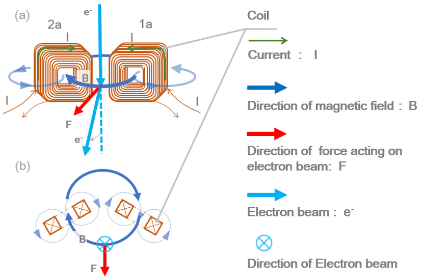
図1 コイルから発生する磁場によって電子線が曲げられる様子。
(a) コイルを二個並べ、それらに逆向きの電流を流すことで磁場Bが発生する。(b)紙面上方から下方に電子線が進むと磁場Bの影響で、電子線に力Fが働き、曲げられる。
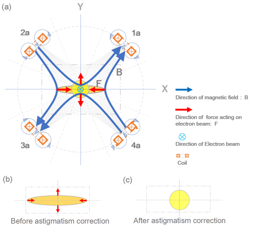
図2 4個のコイルから成る非点収差補正装置の概念図。
4個のコイルから形成される磁場(a)によって、X軸方向に伸びた楕円状の電子線(b)が円形状(c)に補正される。
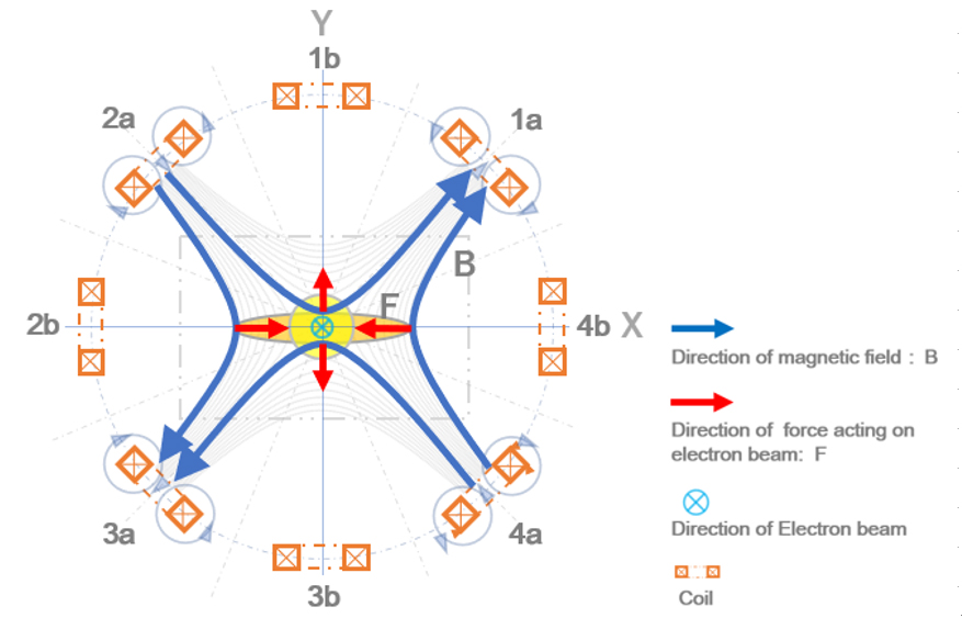
図3 8個のコイルから成る非点収差補正装置の概念図。
図2で示した4個のコイルと同じコイルを45°ずらして配置する。コイルの番号が偶数と奇数はそれぞれ逆向きの電流を流す。コイルaとb には、それぞれ同じ電流を流す。電流量を調整することにより、非点収差が補正される。
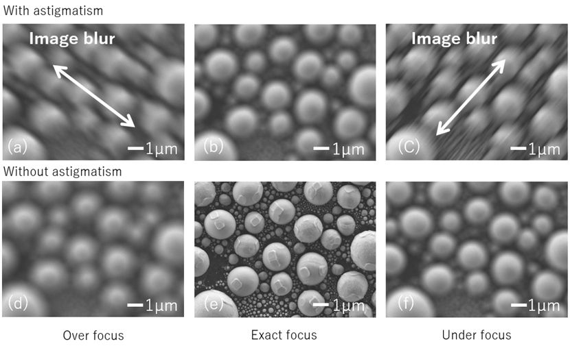
図 4 非点収差を補正しない電子線と補正した電子線に対して、フォーカスを変化させた場合のSEM像の変化。
非点収差がある場合には、(a) オーバーフォーカスと (c) アンダーフォーカスで、直交する方向に像の広がり (矢印の方向へ像の伸び)が生じている。(b) エグザクトフォーカスでは、ボケの量は両方向で等しいが、試料の輪郭が不明瞭な像になっている。
非点収差を補正した場合には、(d) オーバーフォーカスと (f) アンダーフォーカスで像のぼやけかたは等方的になり、(e) エグザクトフォーカスでは、試料の輪郭にボケのない明瞭な像が得られる。
試料:カーボンペレット上のスズの球、加速電圧 5 kV、ワーキングディスタンス 4 mm、照射電流量 176 pA。
A stigmator is a device which corrects an ellipse-shaped electron beam caused by the astigmatism of an electron lens to a circular electron beam.
Fig. 1 explains the force exerted on an electron beam due to the magnetic field created by an electric current through a set of coils. Two coils are placed as shown in Fig. 1(a). Coil 1a is connected to coil 2a with a copper wire, where the winding direction of each coil is opposite. When an electric current flows through the coils, the magnetic field B as shown in Fig. 1(b) is generated. Then, when an electron beam runs through the magnetic field B from the top to the bottom of the paper as shown in the figure, a force F acts on the electron beam.
Next, as shown in Fig. 2(a), coil 3a and coil 4a are added, and each coil is placed at intervals of 90°. These coils (coil 1a, 2a, 3a and 4a) are connected with a copper wire. The winding direction of the odd-number coils is opposite to that of the even-number coils. When an electric current flows through the four coils, the direction of the rotation of the magnetic field created by a coil and the coil on its left side is opposite to the direction of the rotation of that created by the coil and the coil on its right side. Consider an ellipse-shaped electron beam extending in the X direction (Fig. 2(b)), which is caused by the astigmatism of a lens, runs at the center of these coils from the top to the bottom of the paper (Fig.2(a)). Then a force that shrinks the electron beam in the X direction and extends it in the Y direction act. As a result, the electron beam is corrected to a circular shape (Fig. 2 (c)).
In the description of Fig. 2, it is assumed that the major axis of the astigmatism is in the middle of the center of the two coils. However, in the real case, the direction of the axis is arbitrary. To correct such an astigmatism, another four coils (coil 1b, 2b, 3b and 4b) are added as shown in Fig. 3. Then, the astigmatism in any direction can be corrected by adjusting the electric current Ia flowing through coils of 1a, 2a, 3a and 4a and the electric current Ib flowing through coils of 1b, 2b, 3b and 4b [1]. It is noted that the stigmator is placed at the electron source side of the objective lens.
Fig. 4(a), (b) and (c) show SEM images suffered by astigmatism. The images taken at an overfocus position (a) and an underfocus position (c) show blur in the directions orthogonal to each other. At the exact focus position (b), blur is isotropic but does not disappear. Fig. 4(e) is an SEM image taken at the exact focus position after the astigmatism is corrected, exhibiting no image blur. After the astigmatism correction, image blur is isotropic even at de-focus positions, as shown in (d) overfocus and (f) underfocus.
Reference:
[1] K. Kanaya and H. Kawakatsu, Deflection System with Eight-pole Stigmator Used in Correcting Astigmatism, Journal of Electron Microscopy, 10 (1961) 218-221.
Fig. 1 Schematic illustration of the deflection of the electron beam due to the magnetic field created by a set of two coils.
(a) Two coils are placed as is shown in the figure, where the winding direction of each coil is opposite. When an electric current flows through the two coils, the magnetic field B is generated. (b) When an electron beam e- runs through the magnetic field B from the top to the bottom of the paper, a force F acts on the electron beam to deflect the beam.
Fig. 2 Schematic of a stigmator which consists of four coils.
A magnetic field shown in (a) created by a set of the four coils corrects an ellipse-shaped electron beam extending in the X direction (b) to a circular electron beam (c).
Fig. 3 Schematic of a stigmator which consists of eight coils.
Four coils 1b, 2b, 3b and 4b that are the same as those shown in Fig. 2 are added and placed at intervals of 45°. The winding direction of the odd-number coils is opposite to that of the even-number coils. The amount of the electric current flowing through coils 1a, 2a, 3a and 4a and the amount of the current flowing through coils 1b, 2b, 3b and 4b, are the same. By adjusting the electric current, the astigmatism of a lens is corrected.
Fig. 4 Change in SEM images at different focal positions with astigmatism and without astigmatism.
When the astigmatism exists, the images taken at an overfocus position (a) and an underfocus position (c) show blur in the directions orthogonal to each other (indicated by arrows). At the exact focus position (b), image blur is isotropic but does not disappear. Thus, the specimen edges are not clear in the image.
When the astigmatism is corrected, image blur is isotropic at an overfocus position (d) and an underfocus position (f). At the exact focus position (e), image blur disappears. Thus, the details of the specimen surface are clearly seen.
Specimen: Ball of tin/Carbon pellet. Accelerating voltage: 5 kV. Working distance: 4 mm. Probe current: 176 pA.
関連用語から探す
説明に「非点収差補正装置」が含まれている用語


