電磁場重畳対物レンズ
電磁場重畳対物レンズ
electrostatic/electromagnetic field superposed objective lens
[目次:装置]
通常の磁場レンズに静電レンズを重畳させて、低加速電圧でも高空間分解能を得るために焦点距離を短くした対物レンズ。
高空間分解能観察を行うには、試料上でのプローブ径を小さくする必要がある。そのためには、対物レンズの収差が小さくなるように加速電圧を高く設定する。しかし、試料の最表面を観察したい場合や高分子材料のように高加速電圧の電子線でダメージを受けやすい試料、さらには帯電しやすい試料を観察したい場合は、低加速電圧(0.5~1.0kV)を用いなければならない。低加速電圧での収差によるプローブサイズの増加を補って空間分解能を改善するには焦点距離を短くする必要がある。焦点距離を短くすると、試料と対物レンズ下部が近づきWD(作動距離)が小さくなりすぎてしまう。通常、数mm程度のWDが必要である。そこで、磁場レンズに静電レンズを重畳すると、WDを犠牲にせずに焦点距離を短くすることができ、磁場単独の対物レンズよりもプローブ径を小さくでき、低加速電圧でも高空間分解能の観察が可能になる。
電磁場重畳対物レンズの構造を図1に示す。磁場型対物レンズの中に加速管と呼ばれる金属パイプが組みこまれている。加速管には磁場型対物レンズに対して正の電圧(数 kV)が印加されている。加速管の下端と磁場型対物レンズの下極の間には、電子線を減速する電場が生じ、静電レンズとして働く。この静電レンズは磁場レンズよりも試料に近いところにできる。加速管の下端は磁場型対物レンズの下極より上側にあるので、WDを変えずに小さなプローブ径を得ることができる(図2)。
この電磁場重畳対物レンズの利点は、アウトレンズ型対物レンズの汎用性を保ちつつ高空間分解能を実現したことにある。大きな試料の傾斜観察、EDSやEBSD分析、特殊ステージ(加熱冷却や引っ張りなど)を組み込んでも、試料と対物レンズとの干渉を起こさずに高空間分解能観察ができる。さらに、磁性体試料も、対物レンズの磁場の影響を受けずに観察することができる。
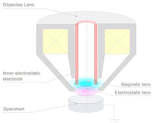
図1 電磁場重畳レンズ
磁場レンズの内部に加速管が設置されている。磁場レンズの下側に静電レンズが形成される。
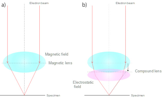
図2 磁場レンズと電磁場重畳レンズの場合の試料上での電子プローブの違い
a) 磁場レンズのみのレンズ作用。電子線は磁場レンズのみによって試料面に集光する。
b) 電磁場重畳レンズのレンズ作用。静電場が磁場レンズの下部にできたことで電子線はさらに強い集束を受けるので、実効的に同じWDを保ったまま、焦点距離が短くなり、小さなプローブができる。
An objective lens where an electrostatic lens is superposed on an ordinary magnetic lens, so as to obtain high spatial resolution even at low accelerating voltage by decreasing the focal length.
For high spatial resolution observation, the electron probe diameter on a specimen needs to be made small. To achieve this, the accelerating voltage is set high so that the aberration of the objective lens becomes small. However, the observation of various specimens, such as the top surface of a specimen, a specimen (high polymer material, etc.) susceptible to thermal damage due to irradiation of a highly-accelerated electron beam and a specimen susceptible to electric charging, requires a low accelerating voltage (0.5 to 1 kV). For improving the spatial resolution while compensating the increased probe size due to the aberration at low accelerating voltage, it is necessary to shorten the focal length. When the focal length is shortened, the specimen position is close to the bottom of the objective lens and thus, the working distance (WD) becomes too short. It is noted that the ordinal WD requires several mm. To overcome this problem, superposing an electrostatic lens on the ordinary magnetic lens makes it possible to shorten the focal length without a very small WD. This feature achieves a smaller probe diameter than that provided by the objective lens which uses only a magnetic field. Thus, the specimen can be observed with high spatial resolution even at low accelerating voltage.
The structure of the electrostatic/electromagnetic field superposed objective lens is schematically explained in Fig. 1. A metal pipe, called "inner electrostatic electrode," is incorporated in the magnetic objective lens. In this electrode, a positive voltage (several kV) is applied to the magnetic objective lens. An electric field, which decelerates the electron beam, is generated between the bottom of the inner electrostatic electrode and the lower pole of the magnetic objective lens. Then, this generated electric field acts as an electrostatic lens. This electrostatic lens is created closer to the specimen than the magnetic lens. Since the bottom of the inner electrostatic electrode is placed above the lower pole of the magnetic objective lens, a small probe diameter is obtained without changing the WD (Fig. 2).
The major advantage of the electrostatic/electromagnetic field superposed objective lens is that high spatial resolution is achieved while maintaining the general versatility of the out-lens objective lens. The use of this unique lens enables high spatial resolution observation in various cases. That is, this superposed lens makes it possible to perform tilt observation of a large specimen, EDS and EBSD analyses, and observation with an added special stage (for heating and cooling, stretching, etc.) while the specimen does not interfere with the objective lens. Furthermore, a magnetic specimen can be observed with no influence from the magnetic field of the objective lens.
Fig. 1 Electrostatic/electromagnetic field superposed objective lens.
An inner electrostatic electrode is placed inside the magnetic lens. An electrostatic lens is created beneath the magnetic lens.
Fig. 2 Difference of the electron probe on the specimen for the magnetic objective lens and for the electrostatic/electromagnetic field superposed objective lens.
(a) Lens action only for the magnetic lens. The electron beam is focused onto the specimen only by the action of the magnetic lens.
(b) Lens action for the electrostatic/electromagnetic field superposed lens. An electrostatic field is generated at the bottom of the magnetic lens and thus, the electron beam is further focused. As a result, the focal length is shortened and a small probe is produced while the same WD is maintained.
関連用語から探す
説明に「電磁場重畳対物レンズ」が含まれている用語


