ウィークビーム法
ウィークビーム法
weak-beam method
[目次:理論(電子の散乱/回折/結像)]
弱く励起した回折波を使って、すなわち動力学効果を少なくした状態で、転位の暗視野像を撮り、転位の像をシャープにする方法。たとえば、系統反射を起こし、次数の高い反射である3次の反射が丁度ブラッグ反射を満たす条件にして、弱く励起されている反射、1次の反射 (ウィークビーム) の暗視野像を撮る。
ウィークビーム法で転位を観察すると、暗いバックグラウンドの中に転位による歪みの大きい部分 (転位芯に近い部分) だけが白黒の点線として現れる。転位像は、強く励起した反射を使うときよりも、シャープになり転位の位置がより正確にわかる。その結果、転位が拡張しているかいないかの判定の精度が上がる。
図aはG反射が励起される二波励起条件 (図c) で撮影した明視野像。図bは図aの黄色線で囲った部分の拡大図。図dは図cの条件で、対物絞りを移動しG反射を選択して (図f) 撮った暗視野像。図eは図dの拡大図。図gは、図cの条件から電子ビームを傾斜して3G反射を励起し (図i)、対物絞りでG反射を選択して撮った暗視野像 (ウィークビームによる暗視野像)。図hは図gの拡大図。試料中の同じ転位を二波励起条件 (図c) で撮影した暗視野像 (図e) では転位像は太い点線として写っているが、ウィークビーム法による暗視野像 (図h) ではシャープになっているのが分かる。
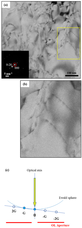
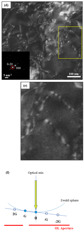
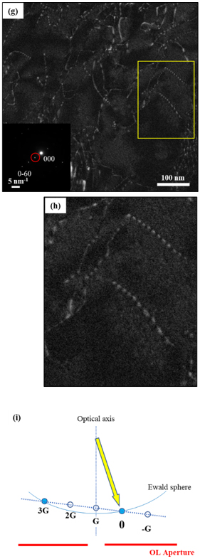
図. Al合金の転位像。
二波励起状態で撮られた明視野像(a)と暗視野像(d)。ウィークビーム法による暗視野像(g)。
図a, d, g中の左下には各像を撮ったときの電子回折図形と対物絞りの位置(赤丸)を示している。
図b, e, hは、それぞれ図a, d, g中に示す黄色矩形領域の拡大像。
図c, f, i に、それぞれ明視野像(a)、暗視野像(d)およびウィークビームによる暗視野像(g)を撮ったときの回折条件および対物絞りの位置(赤線の途切れた場所)を示す。
The weak-beam method is a technique to take a sharp dislocation image using a weakly excited diffraction wave (reflection beam) with decreasing the dynamical diffraction effect. For example, a dark-field image of a weakly excited reflection (weak beam), e.g. of the first-order reflection, is taken at the exact Bragg setting of a high-order reflection, e.g. the third-order reflection, under a systematic reflection condition.
When a dislocation is observed using the weak-beam method, only highly strained parts of the dislocation (close to the dislocation core) appear as a black-and-white dotted line against dark background. Thus, the dislocation is more sharply imaged and the position of the dislocation is more accurately determined than when using a strongly excited reflection. As a result, the accuracy of determining whether a dislocation is extended or not is improved.
Fig. (a) shows a bright-field image taken under a two-wave excitation condition where reflection G is excited (Fig. (c)). Fig. (b) is an enlarged image of the part enclosed by a yellow square line in Fig. (a). Fig. (d) shows a dark-field image taken under the condition of Fig. (c) by shifting the objective aperture to select reflection G (Fig. (f)). Fig. (e) is an enlarged image of the part enclosed by a yellow square line in Fig. (d). Fig. (g) shows a dark-field image taken by the weak-beam method. That is, an electron beam is tilted from the condition of Fig. (c) to excite reflection 3G (Fig. (i)), and reflection G is selected with the objective aperture. Fig. (h) is an enlarged image of the part enclosed by a yellow square line in Fig. (g).
The dislocation images in Fig. (e), which were taken under a two-wave excitation condition or with a strongly excited reflection (Fig. (c)), are viewed as thick dotted lines. On the other hand, it is seen that the images taken by the weak-beam method (Fig. (h)) are sharpened.
Figs. Bright- and dark-field images of dislocations in an Al alloy.
(a) a bright-field image and (d) a dark-field image taken under a two-wave excitation condition. (g) a dark-field image taken by the weak-beam method. On the lower left corner of each image (Figs. (a), (d) and (g)), an electron diffraction pattern and the position of the objective aperture (indicated by red circles) when each image was taken, are shown. Figs. (b), (e) and (h) show the enlarged images of yellow rectangular areas in the three respective images (a), (d) and (g). Figs. (c), (f) and (i) respectively show the diffraction conditions and the positions of the objective aperture (positions where the red lines are interrupted) for the bright-field image (a), the dark-field image (d) and the weak-beam dark-field image (g).
関連用語から探す
説明に「ウィークビーム法」が含まれている用語


