コマ収差(軸外)
コマ収差(軸外)
(off-axial) coma aberration
[目次:レンズ系]
物面の光軸から距離rだけ離れた点から光軸に対していろいろな角度αで出射した電子線がレンズを通ったあと、像面上で1点に結像せず円錐状(彗星状)の像を作る収差。円錐の頂角(彗星の尾の開き角)は60°になる。ザイデルの5収差の一つでレンズに固有な収差である。その大きさはrα2に比例する。軸外コマ収差はザイデルの5収差の中で、対物レンズでは理論上、α3に比例する球面収差に次いで、像のぼけに対して影響が大きい。コマの名称はcomet(彗星)に由来する。実際には、通常の高分解能観察のみならず低倍率像観察でも、軸外コマ収差による像のボケは現在のところ無視できる場合が多い。なお、寄生収差である軸上コマ収差(α2に比例する)とは別物である。
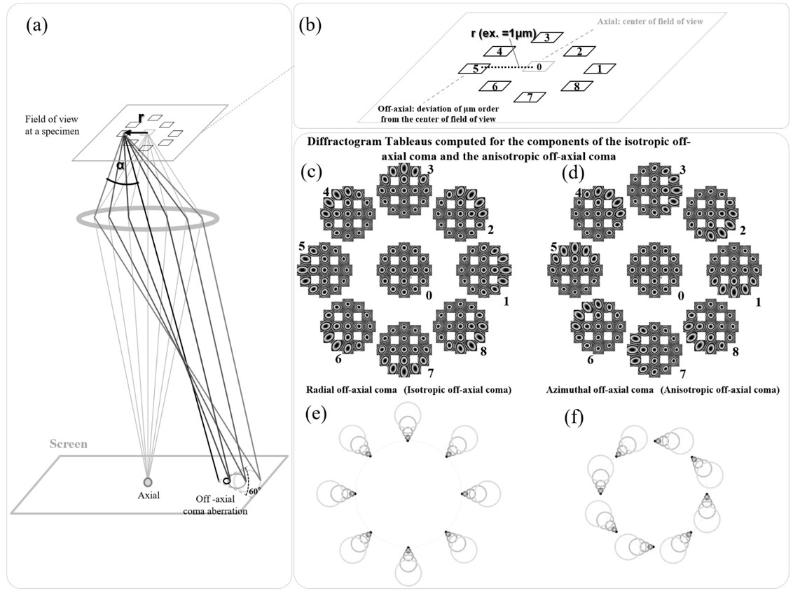
軸外コマ収差は、軸上中心からある距離r離れた領域での軸上コマ収差と等価である。その大きさと方向は、中心から単位距離(例えば1µm)離れた視野でαを変化させて撮影した図形(Diffractogram Tableau)で計測できる(図a,b)。軸外コマ収差の動径成分(等方成分)と方位角成分(非等方成分)をそれぞれ図cと図dに示した(ただし、これらは実測したものではなく、見やすくするために計算した例である)。図cおよび図dに対応する実空間での像のぼけ(円錐状形状のビームの広がり)を、図eおよび図fに模式的に図示した。
磁場型軸対称レンズの場合、発生する軸外コマ収差には、動径成分(図c)と磁場による電子線の回転効果(ラーモア回転)のために発生する方位角成分の両方がある(図d)。電場型レンズの場合(可視光学におけるレンズの場合も)は、電場では電子線の回転効果がないので、動径成分(図c)のみである。
軸外コマ収差補正の例はある。しかしながら、透過電子顕微鏡観察(TEM)における低倍率像(広視野像、rが大きい)では、像の拡大率が低く、軸外コマ収差による像のぼけはカメラの画素の大きさに比べて小さい。例えば、観察視野の大きさが4µm(光軸上から±2µm)で画素数4千×4千のカメラを用いた場合、1画素当たりの像のサイズは1nmとなるが、軸外コマ収差によるぼけの大きさは1~2画素以下となり、収差の影響が像に現れることは少ない。また、高分解能像観察では、観察視野が狭い(rが小さい)ため、rに比例する軸外コマ収差は非常に小さくなる。例えば、観察視野の大きさが50nm(光軸上から±25nm)では、軸外コマ収差によるぼけの大きさは0.1nm以下程度となる。したがって、高分解能観察の場合でも軸外コマ収差画像の劣化を引き起こすことはない。
STEMの場合は、収差があるとプローブがぼける(大きくなる)ため、STEM像の分解能は下がる。しかし、TEMと同様に、低倍率STEM像(スキャンする範囲rが大きい)での軸外コマ収差によるプローブのぼけ量はカメラの1画素当たりの像のサイズに比べて小さいたいため、像のぼけとして現れることは殆どない。また、高分解能STEM像(原子分解能像)の場合はスキャンする距離r(観察領域)が小さいため、軸外コマ収差によるぼけ量は、像の分解能を下げるほど大きくはならない。
ただし、単粒子解析や半導体不良解析の場合に、視野を変えながら多くの高分解能TEM像を取得する場合がある。その場合、試料を機械的に移動すると試料ドリフトが収まるまでの待時間が必要になる。それを避けるために試料下部の偏向系で視野を移動させることがある(例えば、図(b)において軸外に位置する視野“5”を、軸上中心位置“0”に移動させる)。その際、視野の光軸からの移動距離が大きく(数µm程度)なることがあり、軸外コマ収差が像質に影響を及ぼす。このような場合、軸上中心に移動した視野に対して(照射系の)コマフリー軸合わせを行って、収差の影響を低減することがある。
Electron beams which exit from a point on the object plane with a distance r from the optical axis at various angles α with respect to the optical axis, do not come to a single point on the image plane after passing through the lens but produce a cone-shaped (comet-shaped) image. This phenomenon is called the off-axial coma aberration. The name of “coma” originates from “comet”. This aberration is proportional to rα2. The vertex angle of the cone is 60°. The off-axial coma aberration is inherent to the lens and is one of “Five Seidel aberrations”. In the case of the objective lens, the spherical aberration which is proportional to α3 has the largest contribution to the image blur. The off-axial coma aberration theoretically has the second largest effect on the blur among Five Seidel aberrations. However, in fact, the blurring of images due to the coma aberration can be ignored not only in high-resolution imaging but also in low-magnification imaging.
It is noted that the off-axial coma aberration is a different aberration from the axial coma aberration (proportional to α2), which is one of parasitic aberrations.
The off-axial coma aberration is equivalent to the axial coma aberration (proportional to α2) at the distance r from the optical axis. The magnitude and direction of the off-axial coma aberration can be measured using Diffractogram Tableaus (Fig. (a), (b)) taken by changing α at a unit distant (e.g. 1 µm) from the optical axis. Fig. (c) and (d) show the radial (isotropic) components and the azimuthal (anisotropic) components of the off-axial coma aberration (These are not measurement results but computed examples for ease of understanding). Fig. (e) and (f) schematically show the image blurs (cone-shaped beam broadenings) in the real space corresponding respectively to Fig. (c) and (d).
In the case of an axially symmetric magnetic-field lens, the off-axial comma aberration contains the radial components (Fig. (c)), and the azimuthal components arising from a rotation effect (Larmor rotation) of the electron beam due to the magnetic field (Fig. (d)). In the case of an electric-field lens (including visible-light lens), the off-axial coma aberration contains only the radial components because there is no rotation effect of the electron beam in the electric field (Fig. (c)).
An example of correction of the off-axial coma aberration has been reported. However, in the case of low-magnification imaging (large-field imaging with a large r) in transmission electron microscopy (TEM), the magnification rate is low and thus, image blur due to the off-axial coma aberration is small. For example, when the size of the observation area is 4 µm (the distance from the optical axis being ±2 µm) and an imaging camera with 4000 × 4000 pixels is used, the image size at one pixel is 1 nm, and the image blur due to the off-axial coma aberration becomes less than one to two pixels. Thus, the effect of this aberration is small on the low magnification image. In the case of high-resolution imaging, the observation area or the distance r is small. Thus, the off-axial coma aberration becomes very small. For example, when the size of the observation area is 50 nm (the distance from the optical axis being ±25 nm), the off-axial coma aberration becomes to be 0.1 nm or less. Thus, the effect of this aberration is very small on the high magnification image.
In the case of STEM, aberrations cause blurring of the probe or the probe blur, which reduces the resolution of STEM image. However, at low magnification STEM imaging (large scanning area with a large r), the amount of the probe blur due to the off-axial coma aberration is small compared to the image size at a single pixel of the imaging camera, thus blurring of the image hardly appears. At high-resolution (atomic resolution) STEM imaging, as the scanning distance r or the observation area is small, the image blur due to the off-axial coma aberration is not large enough to reduce the image resolution.
However unlike the above-mentioned cases, the off-axial coma aberration can decrease image quality at image acquisition in single particle analysis and semiconductor failure analysis. For those analyses, a great number of high-resolution TEM images are acquired while varying the field-of-view. During the acquisition, mechanical moving of the specimen requires a waiting time until the specimen drift stops. To avoid such a waiting time, the field-of-view is often moved using the deflector beneath the specimen (For example in Fig. (b), the field-of-view “5” at an off-axial location is moved to the optical axis or the position “0”). If the field-of-view is distant (about a few µm) from the optical axis, the off-axial coma aberration can degrade the image quality. When the aberration effect arises, alignment of the coma-free axis of the illumination lens system is carried out for the field-of-view moved to the optical axis to reduce the aberration effect.
関連用語から探す
説明に「コマ収差(軸外)」が含まれている用語


