大角度収束電子回折法
大角度収束電子回折法
large-angle convergent-beam electron diffraction, LACBED
[目次:理論(電子の散乱/回折/結像)]
通常の収束電子回折法では隣接する回折波のために回折ディスクの半径はブラッグ角を越えることができない。大角度収束電子回折法を用いると、角度に関するこの制限を越えて大きな角度の収束電子回折図形が得られる。C-Oレンズを使って、入射ビームの焦点に試料を置くと像面(制限視野絞り)上に明視野像と暗視野像の重なった像ができる。試料位置をビームの焦点からはずして上方または下方にずらすと制限視野絞り上の明視野像と暗視野像は分離する。制限視野絞りで、たとえば明視野像のみを選んで、中間レンズの条件を回折図形を得るモードに設定すると、通常の収束電子回折図形の角度の3~4倍にわたる明視野の回折図形が得られる。大角度収束電子回折図形には像と回折図形の両方の情報が入っており、格子欠陥の同定や界面の歪解析に有効に使われている。
LACBED (a)(b)⇒図
(a)収束半角をブラッグ角以下にした場合
通常の収束電子回折法では、隣接する回折波が互いに重ならないようにするために、収束半角αはブラッグ角θ以下に設定する。
(b) 収束半角をブラッグ角以上にした場合
収束半角αがブラッグ角θを越えると、隣接する回折波ディスクと重なり、それぞれの回折波の情報が取り出せなくなる。
LACBED (c)(d)⇒図
(c) 通常の収束電子回折法で収束角をブラッグ角より大きくした場合の光線図。
通常の収束電子回折法では、入射ビームの焦点に試料を置き、対物レンズのピントを試料に合わせる。その場合、対物レンズの後焦点面に回折図形が形成され、試料の像(この場合はスポット状の像)は制限視野絞り上に形成される。入射電子線の収束角をブラッグ角より大きくした場合、対物レンズの後焦点面で回折図形は透過波ディスクと回折波ディスクが重なる。透過波および回折波による試料の像は制限視野絞り上で重なる。
(d) 大角度収束電子回折法での光線図。
①大角度収束電子回折法では、対物レンズの励磁の強さを変えずに試料位置を入射ビームの焦点から上方に(または下方に)ずらす。
②回折図形は(c)の場合と同様に、対物レンズの後焦点面にできているが、制限視野絞りの位置にあった試料の像は上方に(または下方に)ずれ、透過波像(スポット)と回折波像(スポット)は制限視野絞り上で分離する。
③ここで、結像系(中間レンズ)で像を観察するモードで制限視野絞りを用いて、たとえば透過波スポットのみを選ぶ。ここで、回折図形を観察するモードに結像系(中間レンズ)を切り替えると、重なりのない、透過波のみで形成された、回折角の制限を超える大角度の収束電子回折図形が得られる。
大角度収束電子回折図形⇒図
加速電圧:200kV, 試料:Si [111]
In conventional CBED, if the angular diameter of a diffraction disk exceeds the Bragg angle, the disk overlaps with an adjacent diffraction disk. Thus, the angular diameter is limited to an angle smaller than the Bragg angle. The use of the large-angle convergent-beam electron diffraction (LACBED) technique breaks through the angular limitation. Using a condenser-objective (CO) lens, when a specimen is placed on the focus position of the CO lens, the bright-field and dark-field images are formed on the image plane (on the selected-area aperture) but these images overlap with each other. When the specimen is shifted upper or lower from the focused position of the incident beam, the bright-field and dark-field images on the selected-area aperture are separated. If only the bright-field image is chosen with the selected-area aperture and the intermediate lens is set to take a diffraction pattern (the diffraction mode), the bright-field diffraction disk covers an angle of three to four times larger than that for the conventional CBED disk. Since the LACBED pattern contains information on both the image and diffraction pattern, it is effectively utilized for identification of lattice defects and analysis of strains at interfaces.
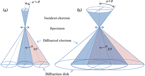
(a) In the case of convergence semi-angle to be equal to the Bragg angle or smaller.
In conventional CBED, the convergence semi-angle a is limited at the maximum to the Bragg angle θ to avoid the overlap of adjacent diffraction disks.
(b) In the case of the convergence semi-angle to be larger than the Bragg angle.
When the convergence semi-angle a exceeds the Bragg angle θ, the adjacent diffraction disks overlap, thus making it impossible to extract information on each diffraction disk.
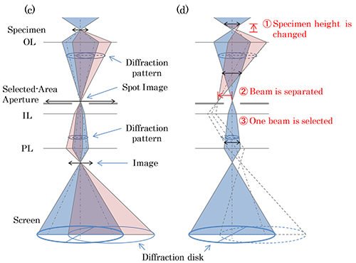
(c) Ray diagram of conventional CBED where the convergence semi-angle is set to an angle larger than the Bragg angle.
In conventional CBED, the incident beam is focused on a specimen and the objective lens is focused on the specimen. A diffraction pattern is formed on the back focal plane of the objective lens and an image of the specimen (a spot image in this case) is formed on the selected-area aperture. When the convergence semi-angle of the incident electron beam is set to an angle larger than the Bragg angle, a transmitted wave disk and diffracted wave disks overlap with each other on the back focal plane of the objective lens. The image formed by the transmitted wave and images formed by diffracted waves are superposed on the selected-area aperture to form a spot image.
(d) Ray diagram of LACBED.
①In LACBED, the specimen position is shifted to a higher (lower) position from the focused position of the incident beam without changing the excitation of the objective lens.
②The diffraction pattern is formed on the back focal plane of the objective lens as it is in (c). The image of the specimen, which is formed on the selected-area aperture in (c), is shifted to an upper (lower) position, and on the selected-area aperture the (spot) image of the transmitted wave and (spot) images of the diffracted waves are separated.
③If only the transmitted spot (beam) is selected using the selected-area aperture in the image observation mode of the intermediate lens system, and then the intermediate lens system is switched to the diffraction mode, a large-angle convergent-beam electron diffraction (LACBED) pattern formed only by the transmitted wave is obtained. The LACBED pattern removes the overlap due to the diffracted wave disks and extends its angular diameter beyond the limitation of the diffraction (Bragg) angle.
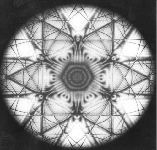
LACBED pattern of Si [111] taken at an accelerating voltage of 200 kV.
関連用語から探す
説明に「大角度収束電子回折法」が含まれている用語


