ディフラクティブイメージング
ディフラクティブイメージング
Diffractive imaging
[目次:理論(電子の散乱/回折/結像)]
試料の回折図形からその像を再構成する手法。回折図形では収差の影響が少ないため、原理的には、得られる試料構造像の分解能は、取得する回折図形の最大回折角で決まり、レンズを使った高分解能像より高い分解能の試料構造像(振幅像と位相像)が得られる可能性がある。この手法はX線で盛んに研究されており、X線分野ではCoherent Diffractive Imaging(コヒーレント回折イメージング)と呼ばれている。電子線分野では、Diffractive Imaging(回折イメージング)、回折顕微法と呼ばれることが多い。カーボンナノチューブなどに応用され0.1nm程度の分解能が得られている。また、結晶に限らず、単一分子など非周期構造の試料にも適用できる。像の再構成には、フーリエ反復位相回復法を用いる。すなわち、試料から得た回折図形の強度の平方根を取って回折振幅とし、ランダムな初期位相を与えてフーリエ変換して試料の近似像を得る。得られた像には、試料外形を超える領域にも構造が現れる。試料外形がはっきり決められる場合はその領域以外の強度を0とおいて(実空間拘束条件)、(試料の外形を正確に決めにくいときは試料より少し大きな領域(サポートと呼ぶ)を規定し、サポートを超えた領域の強度を0とおいて)、これを逆フーリエ変換して回折図形を得る。得られた回折強度が実験値と不一致の場合は、回折振幅を実験値に置き換えて(逆空間拘束条件)、再びフーリエ変換して実像を得る。このような操作を繰り返すことで徐々に正しい位相を回復して、試料の真の構造像が得られる。正しい位相が回復されるまでの反復回数は数1000回以上である。得られる像の精度には、回折図形に含まれる原点まわりの非弾性散乱、検出系や電気回路のノイズ、サポート形状などが影響する。回折図形を取得する際、試料面積(サポート)の2倍以上の領域にビームを照射する。これは回折図形を2倍に細かい間隔でサンプリングすることに対応しており、試料に含まれるすべての情報を取り出すことができ、オーバーサンプリング条件と呼ばれている。実験においては、再構成する対象試料の周囲に試料が存在しない領域を作りだし、オーバーサンプリング条件を満たすように回折図形を記録する必要がある。
Diffractive imaging⇒図
フーリエ反復位相回復法の概念図。フーリエ変換を使って逆空間(回折面)と実空間(像面)を行き来しつつ拘束条件を与えることで、試料の正しい構造像を徐々に求めていく。具体的には、①回折図形から求めた逆空間振幅とランダムな初期位相を与えて逆空間波動場を作成する。②それをフーリエ変換し、実空間波動場にする。③サポートの外の領域の強度をゼロに置き換える(もしくはゼロに近い値にする)。④逆フーリエ変換により逆空間波動場にする。⑤振幅を回折図形から求めた値に置き換える。以上のステップを繰り返すことで、徐々に逆空間での波動の位相および実空間での波動場が正しく求められ、⑥試料構造像を再構成することができる。
"Diffractive imaging" is a method to reconstruct a structure image of a specimen from a diffraction pattern of the specimen. Since the diffraction pattern is less influenced by lens aberrations, the resolution of the structure image obtained is determined by the maximum diffraction angle of the diffraction pattern, thus a higher-resolution structure image (amplitude image and phase image) than a HREM image (taken by using lenses) can be obtained. This method has actively been studied in the field of X-ray diffractometry, the method being called "Coherent Diffractive Imaging." In electron microscopy, the method is called "Diffractive Imaging" or "Diffractive Microscopy." The method has been applied to carbon nanotubes, etc., and a spatial resolution around 0.1 nm has been obtained. In addition, the method can be applied to not only crystals but also non-periodic structure specimens such as a single-molecule specimen. To reconstruct the image, the Fourier repetitive phase recovery method is used. That is, the magnitudes of the diffraction amplitudes are calculated by the square root of the diffraction intensities taken from a specimen, and random initial phases are given to the diffraction amplitudes. Then, the diffraction amplitudes with the phases are Fourier-transformed to obtain an approximate structure image. The obtained image exhibits structures even in areas exceeding the specimen area from which the diffraction pattern was taken. When the external shape of the specimen is clearly determined, the image intensities from areas except for the external dimension are set to be 0 (zero) (real-space constraint conditions). (On the other hand, when it is difficult to accurately determine the external shape, a specimen area (called "support") that is slightly larger than the external dimension is defined, and the image intensities from areas exceeding the support are set to be 0. Then, the image is inverse-Fourier-transformed to a diffraction pattern. The diffraction amplitudes that do not match the experimental amplitudes are replaced with the experimental values (reciprocal-space constraint conditions), and then Fourier transform is applied again to obtain a structure image. As this procedure is repeated, the true phases of the specimen are gradually recovered and finally, a true structure image of the specimen is obtained. The number of iterations until the recovery of the true phases exceeds several thousands of times. The accuracy of the obtained image is influenced by the parameters such as inelastic scattering contained around the origin of the diffraction pattern, noise from the detection system including its electronic circuits, and the external dimension of the support. It should be noted that when taking the original diffraction pattern, an area of twice the specimen area (support) must be illuminated with an electron beam. This means that the diffraction pattern is sampled with steps twice as small as those corresponding to the original specimen size, enabling us to extract all information contained in the specimen, which is called the over-sampling condition. In an actual experiment, it is needed to create an area where no specimen exists around the specimen and to record a diffraction pattern so as to satisfy the over-sampling condition.
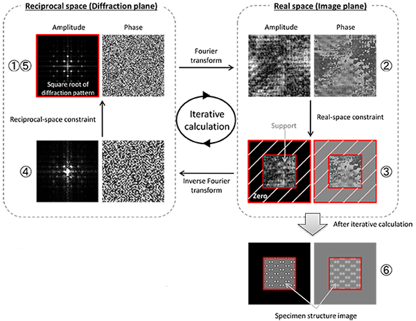
Conceptual diagram of the Fourier repetitive phase recovery method for diffractive imaging. A crystal structure image of a specimen is retrieved from an experimental diffraction data with a good accuracy by applying Fourier transform to the reciprocal space data and then inverse Fourier transform to the obtained real space data repeatedly with giving constraint conditions at each step. To be precise, 1) First, a wave field in the reciprocal space is created by using the diffraction amplitudes obtained from a diffraction pattern and giving random initial phases to the diffraction amplitudes. 2) The wave field formed in the reciprocal space is Fourier-transformed to an image in the real space. 3) The intensities of the image outside the support area are set to be 0 (zero). 4) The corrected image is inverse Fourier-transformed to a wave field in the reciprocal space. 5) The amplitudes of the wave field are replaced to those of the experimental diffraction pattern. Repetition of this cycle enables us to accurately retrieve the phases of diffraction spots in the reciprocal space and the wave field in the real space. 6) Finally, an accurate structure image of the crystalline specimen is reconstructed.
説明に「ディフラクティブイメージング」が含まれている用語


