電子線ホログラフィー
電子線ホログラフィー
electron holography
[目次:理論(電子の散乱/回折/結像)]
電子波の干渉性を利用し、試料によって電子波が受ける位相変化を再生する手法。先ず、試料を透過して位相変化を受けた波(物体波)と電子光源から真空を通過し試料の影響を受けない波(参照波)を、電子線バイプリズムで偏向させ、干渉させて縞(ホログラム)を得る。次に、得られたホログラムをコンピューターでフーリエ変換し、バックグラウンドを作る等間隔の主干渉成分をマスクして取り除き、試料を透過した回折波の変調成分(サイドバンド)を抽出して逆フーリエ変換を行うことにより、試料下面での位相が再生される。
透過型電子顕微鏡でホログラムを得るためには、干渉性の高いビームが必要なため、電子光源が小さい電界放出型電子銃が不可欠である。もともとはD. Gaborによって電子顕微鏡の収差を除くために考えられた(1971年ノーベル物理学賞)手法であるが、現在は微小領域の電場や磁場の観察に広く用いられている。
electron holography⇒図
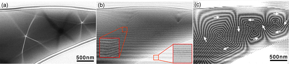
急冷した磁性材料Fe73.5Cu1Nb3Si13.5B9の(a)ローレンツ電子顕微鏡像、(b)ホログラム、(c)位相再生像。
(a)のローレンツ像では磁区の境界(磁壁)が明線または暗線となって現れている。焦点ずらし(デフォーカス)量を大きくするとこの明暗線の幅は太くなる。また、デフォーカスの向きを逆にすると明暗線のコントラストは逆転する。 (b)には、試料を透過した電子線(物体波)と真空中を透過した電子線(参照波)を電子線バイプリズムを用いて干渉させてできた干渉縞が見られている。
写真左部の大きな□部分は小さな□部分の拡大図で、試料内部からの干渉縞を示す。電子線は試料によって場所に依存する位相変化を受け、干渉縞に曲がりや縞間隔の変化がみられる。なお、写真右下部の大きな□部分は小さな□部分の拡大図で、試料を通過しない真空領域からの干渉縞を示す。試料からの位相変化を受けないため、干渉縞は等間隔で直線的である。(c)の位相再生像の黒白線が等位相線であり、磁性体の場合、この方向が磁束の方向(白矢印)を示し、線の間隔が磁束の大きさを表している。等位相線がほぼ直線で同じ向きの領域が一つの磁区を表し、等位相線が大きく屈曲している部分が磁壁を表している。ホログラムから得られた(c)の等位相線が屈曲している場所とローレンツ顕微鏡像(a)の明暗線の場所が一致していることが分かる。
(画像提供: 東北大学 進藤大輔教授)
"Electron holography" is a technique to reconstruct phase changes suffered by a specimen by utilizing the coherency of electron waves.
The scattered wave transmitted through the specimen (object wave: suffering a phase change) and the wave traveling from the electron source and passing through vacuum (reference wave: not influenced by the specimen) are deflected by an electron bi-prism and superposed each other, and then interference fringes or an electron hologram is formed. By applying Fourier transform to the obtained hologram using a computer, a spectrum of the hologram is obtained. Then, the equally spaced, main interference components forming the background in the present case are removed by masking, and modulation components due to the specimen or the diffracted waves (the side-band spectra) are extracted. The modulation components are subjected to inverse-Fourier transform. As a result, the phase changes at the bottom plane of the specimen are reconstructed.
A field-emission electron gun with a small electron source is required because a highly coherent beam is crucial to obtain the hologram. This technique was proposed by Gabor (awarded Nobel Prize in Physics in 1971) to remove aberrations in a TEM. However, nowadays the electron holography technique is widely used for observation of electric and magnetic fields in a very small (micro- to nano-meter scale) specimen area.
(a) Lorentz TEM image, (b) Electron hologram and (c) Phase reconstruction image of a rapidly frozen magnetic material Fe73.5Cu1Nb3Si13.5B9.
In the Lorentz TEM image (a), the boundaries of a magnetic domain (magnetic domain walls) appear as bright or dark lines. Increasing the defocus broadens the width of the bright and dark lines. When the sign of defocus is reversed, bright lines and black lines are interchanged. In the electron hologram (b), interference fringes are observed, which are obtained by deflecting the wave transmitted through the specimen (object wave) and the wave transmitted in vacuum (reference wave) using an electron bi-prism so as to be superposed each other.
The large square at the left shows an enlarged image of the small square area. Interference fringes between the object wave and the reference wave are seen, where the bend and spacing change of the fringes are found. A large square at the bottom right shows the enlarged image of the small square area, where the interference fringes at the vacuum region are seen. Since there is no phase change due to the specimen, these interference fringes are equally spaced and straight.
Bright or dark lines in the phase reconstruction image (c) show equi-phase lines. The directions of the lines indicate the directions of magnetic flux (shown by white arrows) and fringe spacings show the magnitudes of the magnetic flux. A region where the equi-phase lines are almost straight and arranged in the same direction exhibits one magnetic domain. Magnetic domain walls exist at the sudden bends (~90 degrees) of the equi-phase lines. It is found that the sudden bends of equi-phase lines in the electron hologram (c) correspond to the bright or dark lines in the Lorentz TEM image (a).
(Courtesy of the images: Professor D. Shindo, Tohoku University)
関連用語から探す
説明に「電子線ホログラフィー」が含まれている用語


