収差
収差
aberration
[目次:レンズ系]
電子光学系における理想的な結像では、物面の1点からいろいろな方向に出た電子線がレンズを通った後に像面の1点に結像されるが、実際には像面の1点には電子が集まらずぼける。理想的な結像からのこのずれ(“ぼけ”)を収差と言う。収差は幾何収差と色収差に大別される。幾何収差は、物面上の位置や物面から出る電子線の角度に依存した収差であり、光軸からの距離rと光軸となす角度(開き角)αの関数で表される。その中で開き角αのみに依存する収差を軸上幾何収差と言い、光軸からの距離rに、またはrとαの両方に、依存する収差を軸外幾何収差と呼ぶ。一方、色収差は、電子線のエネルギーが単一でなく、エネルギーに広がりがあるときに生じる収差である。すなわち、電子線のエネルギーが異なると、磁場や電場でできたレンズを通ったときに電子線の曲げられ方が異なるために生じる。
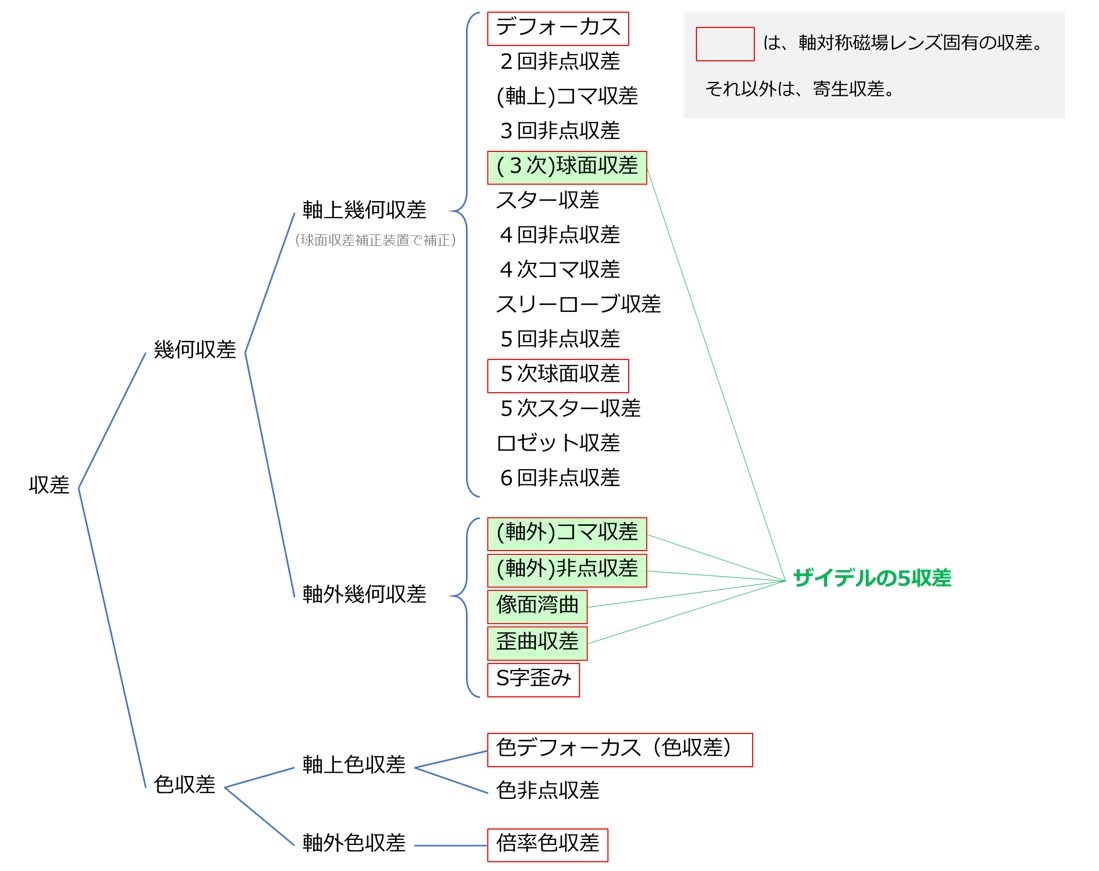
収差の一覧を表1に示す。電子顕微鏡のレンズでは、通常、磁場レンズが用いられ、これらのレンズは光軸に対称な場を持っており、表1の赤枠で囲まれた収差が発生する。特に、緑で示した収差はザイデルの5収差と呼ばれ、光学の原理上、避けられない幾何収差である。それに加えて、磁場レンズでは像を回転させる作用も持つため、視野の周辺部で像が回転するS字歪み(r3に比例)が発生する。そのほかの収差は寄生収差と呼ばれ、レンズのポールピースの材料の不均質性や機械加工の精度、レンズ間の光軸の不一致などに起因する。
電場を使った静電レンズは電子銃で用いられる。この静電レンズも光軸に対称な場を持っており、磁場レンズと同様の収差が発生する。しかし、静電レンズは電子線を光軸の周りで回転させる作用はないため、S字歪みや、軸外収差の方位角方向成分は発生しない。
収差の補正には磁場の多極子が用いられる。偏向素子には双極子が用いられる。双極子場は電子線をある方向に曲げることができるので、レンズ系で起こる軸ずれの補正に使われる。非点補正素子には4極子が用いられる。4極子は2回対称の磁場を作り2回非点収差を発生させる。2つの4極子を異なる角度に配置することで、あらゆる方向の2回非点収差を作ることができ、レンズのもつ非点収差の補正に使われる。また、球面収差補正装置には、4極子や6極子、8極子が用いられる。6極子の場合、6極子に厚みがあるとコンビネーション収差として3次の球面収差が発生する。この球面収差は負の極性を持っており、これを利用して対物レンズの正の球面収差を打消している(コンビネーション収差の項を参照)。6極子自身は主に3回非点収差を発生するが、球面収差補正装置では、逆極性の6極子を直列に配置することで不用な3回非点収差を除去している。
幾何収差
高倍率の高分解能像の観察では、観察する領域が狭くrが小さい範囲に限られるため、軸上幾何収差が重要になる。特に、試料に最も近い対物レンズの3次球面収差(ザイデルの5収差の1つ)の影響が大きい(軸上幾何収差の項を参照)。3次球面収差の大きさは試料上でCsα3と表される。ここでCsは球面収差係数で対物レンズのポールピースに固有の値である。したがって、球面収差係数Csが小さい対物レンズのポールピースを作ることは重要である。非常に良く設計された対物レンズのポールピースではCs~0.5mmになっている。ちなみに、収束半角αを実際に使われる10mradとすると球面収差Csα3 による(像またはプローブの)ぼけは、最小錯乱円で考えた場合(1/2)・Csα3と与えられ、0.25nmとなる。さらに、収束半角を大きくとり25mradと仮定すると、球面収差によるぼけは4nmにもなる(ただし、回折収差は0.1nm以下になる)。球面収差補正装置を電子顕微鏡に搭載した場合は、球面収差係数をゼロにできる。球面収差が除かれると、軸上寄生収差の除去が重要になる。球面収差補正装置では、軸上寄生収差の中で寄与の大きい順番に2回非点収差、軸上コマ収差、3回非点収差、スター収差、4回非点収差を補正していくことができる。さらに最新の球面収差補正装置では6回非点収差と呼ばれる寄生収差も補正でき、開き角αが大きい電子線(~60mrad)を取り込んでも像面の一点に電子線を集光することができるようになった。
他方、低倍率で広い視野(およそ10µm×10µm以上)、すなわち光軸から大きく外れた視野を観察する場合には、軸外幾何収差が重要になる。結像レンズ系の下段にあるレンズ、すなわち中間レンズと投影レンズの軸外収差が像の劣化(歪みやぼけ)に大きく影響する。これは、レンズで像が拡大されるほど、拡大像の周辺部では光軸からの距離rが大きくなるためである(軸外幾何収差の項を参照)。軸外幾何収差としては、ザイデルの5収差に含まれる歪曲収差(r3に比例)、像面湾曲収差(r2αに比例)、(軸外)非点収差(r2αに比例)、(軸外)コマ収差(rα2に比例)、および磁場レンズに特有な視野の周辺部で像が回転するS字歪み(r3に比例)がある。これら以外の軸外収差(寄生収差)は小さく実用上問題にならない。
なお、幾何収差は、実際の結像点の理想結像点からのずれを、電子軌道のずれで表しているが、実際の結像の際の波面を理想的な波面(球面波の波面)からのずれで表した波面収差を用いることもある。幾何収差の方が収差を直観的に理解しやすい一方、波面収差の方がシンプルな数式で表現できる。幾何収差と波面収差では同じ収差が異なる次数で表現される点に注意が必要である。(幾何収差は波面収差をαで微分したものであるため、αの次数が1つ異なる。たとえば、球面収差の場合、幾何収差ではα3に比例する3次の収差として表せるが、波面収差ではα4に比例する4次収差として表される。多くの場合、幾何収差の次数を用いて、3次球面収差と表現される。)
色収差
色収差は、電子線のエネルギーに依存する収差である。電子線のエネルギー(振動数/波長)の違いは、光における色(振動数/波長)の違いに対応するため、光学分野と同様に、電子光学においてもエネルギーの違いによる収差を色収差と表現する。幾何収差と同様に、色収差にも軸上色収差(光軸からの距離rには依存しない色収差)と軸外色収差(光軸からの距離rに依存する色収差)がある。軸上色収差に区分される色デフォーカス(電子のエネルギーの違いによる焦点位置のずれ)のことを単に色収差ということが多い(狭義の色収差)。
色収差(色デフォーカス)による焦点位置のずれの大きさは試料上でCcΔE/Eと表される。Ccはレンズの色収差係数であり、薄肉レンズの場合は焦点距離とほぼ同じ値になる。Eは電子線のエネルギー(加速電圧)であり、ΔEは電子線のエネルギー幅である。エネルギーが異なる電子同士では干渉効果が起きないので、色収差(エネルギーの広がりによる焦点の広がり)は像のコントラストを低下させる。色収差は、電子線のエネルギー幅ΔEを小さくすることで、小さくすることができる。そのためには加速電圧の安定度を高めたり、エネルギーの広がりが小さい電子源を用いたりすることが重要である。(加速電圧の安定度ΔE/Eは1×10-6以下に達している。電子源のエネルギー広がりの幅は、LaB6熱電子銃では~2eV、ショットキー型電子銃では~0.7eV、冷陰極電界放出型電子銃では~0.4eVである。さらに、モノクロメータを用いれば、エネルギー幅を0.1 eV以下にすることもできる。ただし、モノクロメータでは、求めるエネルギー幅を超えるエネルギーをもつ電子をスリットで遮るため、照射電子線量が下がる。)色収差係数の小さなレンズの設計と作製も重要である。球面収差係数Csの場合と同様に、色収差係数Ccは対物レンズのポールピースに固有の値であり、良く設計された対物レンズのポールピースではCc~1mmになっている。色収差を補正する方法として、対物レンズの正の色収差を負の色収差で打ち消してゼロにする色収差補正装置も開発されている。
低倍率で像では、幾何収差の場合と同様に、結像レンズ系の下段にある中間レンズと投影レンズの軸外色収差が効きやすく、軸外色収差が大きいと視野の周辺部で像がぼける。
表1 収差の一覧
The aberration is the deviation from ideal imaging in the electron optical system. In the case of ideal imaging, all the electron beams that exit from a single point on the object plane and pass through a lens meet at a single point on the image plane. However, in the real lens, those electron beams do not meet at the single point but form an image blur. The aberrations are classified into “geometrical aberrations” and “chromatic aberrations”.
The geometrical aberrations depend on the position and the angle of the electron beam exiting from the object plane, and are expressed as a function of r (distance of the electron beam from the optical axis) and α (angle of the electron beam against the optical axis). Among those aberrations, the aberrations which depend only on the angle α are called the axial geometrical aberrations, whereas the aberrations which depend on r, and on both r and α, are called the off-axial geometrical aberrations.
The chromatic aberration is produced when the electron beams do not have a single energy but have an energy spread. That is, the electron beams having different energies are deflected in different angles when passing through the electro-magnetic lens, resulting in the chromatic aberration.
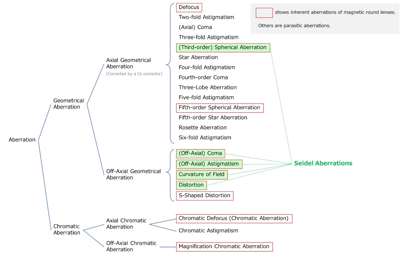
Table 1 lists the aberrations. In usual electron microscopes, magnetic-field lenses are used. These lenses possess a symmetric magnetic field with respect to the optical axis, and cause the aberrations enclosed by red frames. In particular, the aberrations indicated by green colors are called “Five Seidel aberrations”, which are the geometrical aberrations inevitably arising from the principle of optics. Furthermore, since the magnetic-field lens rotates the image, “S-shaped distortion” (proportional to r3) is produced, where the image rotates at the periphery of the field of view. The other aberrations in Table 1 are called “parasitic aberrations” and are caused by magnetic non-uniformity of the pole-piece material, precision of pole-piece machining and disagreement of the optical axes between lenses.
An electrostatic lens utilizing electric field is used in the electron gun. The electrostatic lens possesses an electric field symmetric to the optical axis and generates the aberrations similar to those of the magnetic-field lens. However, the electrostatic lens does not rotate the electron beam around the optical axis and thus, the S-shaped distortion and azimuth components of the off-axial geometrical aberrations are not produced.
Magnetic field multipoles are used for the correction of the aberrations. A magnetic dipole is used in the deflector because it can deflect the electron beam in a certain direction and can compensate the misalignment between the lenses. A magnetic quadrupole is used in astigmatism corrector (stigmator) because it generates a magnetic field with a two-fold symmetry or a two-fold astigmatism. By setting the two quadrupoles at different angles, a two-fold astigmatism in any direction can be created, with which the astigmatism of the lens can be canceled. Magnetic quadrupoles, hexapoles, and octupoles are used for the third-order spherical aberration correctors. In the case of hexapoles, the thick hexapoles produce a third-order spherical aberration as a combination aberration effect (Refer to Term “combination aberration”). This spherical aberration has negative polarity and is used to cancel the spherical aberration with positive polarity of the objective lens. The hexapole itself mainly produces a three-fold astigmatism, but this unnecessary three-fold astigmatism is cancelled out by using two hexapoles of opposite polarity serially.
Geometrical aberrations
In the case of the observation of a high-resolution image at a high magnification, the observation area is small or the distance r from the optical axis of the observation area is small. Thus, in high-resolution imaging, the axial aberrations (not off-axial aberrations) are important for the image quality. In particular, the third-order spherical aberration (one of Five Seidel aberrations) of the objective lens located closest to the specimen has a significant effect. (Refer to Term “axial geometrical aberration”) The amount of the third-order spherical aberration is given by Csα3 on the specimen plane. Here, Cs is the spherical aberration coefficient, the value of which is specific to each polepiece of the objective lens. Thus, it is important to design the objective-lens polepiece with a small Cs. A very-well designed objective-lens polepiece achieves a Cs of ~0.5 mm. For example, when the convergence semi-angle α is taken to be 10 mrad (actually used), the image (or probe) blur or the size of least confusion (1/2) Csα3 becomes 0.25 nm. When the angle is assumed to be 25 mrad, the blur due to the spherical aberration reaches a value of 4 nm, though the diffraction aberration decreases to be less than 0.1 nm.
If a Cs corrector is installed to an electron microscope, Cs of the objective lens can be canceled out to be zero. Once spherical aberration is removed, the next important step is to remove the axial parasitic aberrations. The Cs corrector can correct two-fold astigmatism, axial coma aberration, three-fold astigmatism, star aberration, and four-fold astigmatism, in order of contribution among axial parasitic aberrations. Furthermore, modern Cs correctors can also correct a parasitic aberration called six-fold astigmatism. As a result, electron beams with a large opening angle α (~60 mrad) can be focused onto a single point on the image plane.
On the other hand, the off-axial geometrical aberrations are important when observing a large field of view (approx. 10 µm × 10 µm or more) at a low magnification, or the peripheral region of the observation field distant from the optical axis. The off-axis geometrical aberrations at the lower part of the imaging lens system, i.e. the intermediate lens and the projection lens, have a significant effect on image degradation (distortion and blurring). This is because the more the image is magnified by the lenses, the greater the distance r at the periphery of the magnified image (Refer to Term “off-axial geometrical aberration”).
The off-axis geometrical aberrations include “Distortion” (proportional to r3), “curvature of image field” (proportional to r2α), “off-axial astigmatism” (proportional to r2α) and off-axial coma aberration (proportional to rα2), which are the aberrations in “Five Seidel aberrations”, and “S-shaped distortion” (proportional to r3) which is specific to the magnetic-field lens and rotates the image at the periphery of the field of view. The contributions of the “parasitic” off-axial geometrical aberrations are small and are neglected for practical purposes.
It should be noted that the geometrical aberration is expressed as the deviation of the actual image point from the ideal image point from the deference of the actual electron beam path from the path of ideal imaging. On the other hand, the wave aberration describes aberrations as a deviation of the wavefront in actual imaging with aberrations from the wavefront of ideal imaging with no aberrations (Gaussian imaging). The geometrical aberration is easier to intuitively understand the aberration, but the wave aberrations are expressed by simpler mathematical formulas. It is noted that the geometrical aberration and wave aberration express the same aberration in different orders. (The geometrical aberration is expressed as the derivative of the wave aberration by α. Thus, the order of α differs by 1. For example, the spherical aberration is a third-order aberration proportional to α3 in terms of the geometrical aberrations, but is a fourth-order aberration proportional to α4 in terms of the wave aberrations. In many cases, the spherical aberration is expressed as the third-order aberration according to the order of the geometrical aberration.)
Chromatic aberrations
Chromatic aberration is an aberration that depends on the energy of the electron beam. Since the difference in the electron energy (frequency/wavelength) corresponds to the difference in the color (frequency/wavelength) of light, the aberration due to the difference in energy is called chromatic aberration in the electron optics as in the light optics. Like the geometrical aberrations, the chromatic aberrations include the axial chromatic aberration (not dependent on the distance r of the electron beam from the optical axis) and the off-axial chromatic aberration (dependent on the distance r of the electron beam from the optical axis). Chromatic defocus (change of focus due to difference in electron energy), which is one type of the axial chromatic aberration, is usually called “chromatic aberration” (chromatic aberration in the narrow sense).
The magnitude of the chromatic aberration due to the focus change is expressed as CcΔE/E on the specimen plane. Here, Cc is the chromatic aberration coefficient. In the case of a thin lens, the value of Cc is nearly the same as its focal length. Since the electrons with different energies are incoherent to each other, the chromatic aberration (the focus spread due to the energy spread) causes a reduction in image contrast.
The chromatic aberration can be reduced by decreasing the energy spread ΔE. To achieve this, it is important to improve the stability of the acceleration voltage and use an electron source with a small energy spread. (Modern TEMs achieve the stability of the accelerating voltage ΔE/E to be as high as <1 × 10⁻⁶. The energy spreads of the electron sources are ~2 eV for the LaB6 thermionic-emission electron gun, ~0.7 eV for the Shottky-type electron gun, and ~0.4 eV for the cold field-emission electron gun. If a monochromator is used, the energy spread can be reduced to 0.1 eV or less, though the electron intensity is greatly decreased because the electrons exceeding the required energy spread are blocked by a slit. The design and fabrication of lenses with small chromatic aberration coefficients is also important. As in the case of the spherical aberration coefficient Cs, the chromatic aberration coefficient Cc is specific to the pole piece of the objective lens and is Cc ~ 1 mm for a well-designed objective lens pole piece. As a method of correcting chromatic aberration, a Cc corrector has been developed to cancel out the positive chromatic aberration of the objective lens with the negative chromatic aberration of the corrector to zero.
As in the case of the geometrical aberration, the off-axial chromatic aberration of the intermediate and projection lenses located at the lower part of the imaging lens system can cause image blur at the periphery of the field of view of a low magnification image.
Table 1 List of aberrations
関連用語から探す
説明に「収差」が含まれている用語


