時間分解TEM法
時間分解TEM法
time-resolved transmission electron microscopy, time-resolved TEM
[目次:理論(電子の散乱/回折/結像)]
時間分解TEM法は、物質(試料)の構造の変化を時系列的にイメージングする手法のことである。試料に様々な刺激(加熱、冷却、電場・磁場、応力、レーザー照射など)を与え、その結果、生じる現象を連続電子線やパルス電子線を使って時系列的に観察する。イメージングにおける時間分解能と空間分解能の相関を概念図に示す。現象の時間スケール順に、(a) 数s~msの領域では通常の画像取得用カメラを用いる方法(脚注1)、(b) ms~数10 nsの領域ではダイナミックTEM法(DTEM)、(c) ms~数100 fsの領域では超高速TEM法(UTEM)が用いられる。
(a) 通常の画像取得用カメラを用いる方法
試料の構造変化の時間スケールがカメラの最小露光時間(数ms程度)よりも遅い場合は、連続電子線が使われる。CMOSカメラや直接電子検出型カメラで露光時間を設定し、構造変化を動画として記録することにより時間分解イメージングができる。時間分解能はカメラの露光時間によって決まる。したがって、以下に示すような、試料に対する刺激と照射する電子線を同期させる高度な技法は必要ない。数msより遅い現象であれば、可逆的な現象にも不可逆的な現象にも用いることができる。
(b) ダイナミックTEM法(DTEM)
ダイナミックTEM法では、試料の構造変化がms~数10 nsの時間領域で起こる不可逆的な変化過程をイメージングできる。カメラの露光ではこの時間領域の変化を追えないため、パルス電子線が用いられる。
パルス電子線は、静電偏向器による連続電子線のブランキングや、紫外nsパルスレーザー(たとえば波長250~350 nm)をTaカソードに当てて得られる光電子放出により生成される。1つ目のパルスと2つ目のパルスの間の待機時間はパルス間隔(繰り返し周期)と呼ばれる。パルス間隔とパルス幅はブランキングの速さ(ms~数10 ns)やパルスレーザー(µs~数10 ns)の種類で決まる。また、不可逆な変化を高いS/N比でカメラに記録するには、1パルスあたり106~108個の電子が必要になる。超高出力パルスレーザーを使えば、数10 nsの短いパルス電子線でも106~108個の電子数が確保される。時間分解能はパルス間隔とパルス幅で決まる。
パルス電子線の発生、試料への刺激、カメラによる露光をms~数10 nsの精度で同期させる必要があるため、通常の画像取得用カメラを用いる方法に比べて高度な調整やデータ解析が求められる。
ms~µsの時間スケールの現象の観察には、集束レンズ上部に組み込まれた静電偏向器のブランキングによるパルス電子が利用される。1 µs 以下の時間スケールで起きる現象の観察には、レーザーで光電子放出されたパルス電子が利用される。1パルスあたり106~108個の電子を含むパルス電子列の数は、レーザーの出力に依存し、現在では1 µsあたり最大16個まで生成可能である。この場合、試料を透過した16個のパルス電子列は、像観察室の上部に挿入された静電偏向器により、X-Y方向に(二次元的に)偏向され、カメラの1枚の画面中に16個(4×4)のTEM像または電子回折図形が、時系列的に記録される。16個の各画像サイズは、静電偏向器の制限視野絞りの大きさで決まり、カメラの受光画面全体の1/16の大きさとなるように設定される。この16個の画像からコマ送り動画を生成し、試料の構造変化を観察する。
(c) 超高速TEM法(UTEM)
構造変化の時間スケールがns~fsになると、1パルスあたりの電子数が不足するため、不可逆的な変化過程を観測することはできなくなる。物質の構造変化と緩和が繰り返される可逆的な過程に対しては、超高速TEM法を用いると観察対象の時間スケールがms~fsの範囲にまで広がる。すなわち、この手法は、構造変化と緩和が繰り返し起こる可逆的な現象の観察に限定される。
この場合、パルス電子線は、紫外fsパルスレーザー(たとえば波長250~350 nm)をTaカソード、ガードリング付きLaB6カソード、Wカソードなどに当てて得られる光電子放出によって生成されるほか、高周波キャビティや静電偏向器を使用して連続電子線をチョッピングまたはブランキングする方法で生成される。パルス電子線の発生、試料への刺激、カメラによる露光のタイミングを、パルス幅(たとえば1 ps~200 fs)と同程度の精度で同期させることが求められる。
時間分解能は、ベルシュ効果の影響により、電子数が少ないほど、そして電子線のパルス幅が短いほど向上する。すなわち、レーザー出力を低く抑え、1パルスあたりの電子数を1~100個程度に減らすことで、パルス電子の電子線進行方向の空間的な広がり(パルス幅)を小さくすることが求められる。入射電子数が少なく、カメラのカウント数が減少するので、画像の取得には、パルスレーザーの高い繰り返し周波数(kHz~MHz)を利用して約100万回もの画像を重ね合わせてS/N比を向上させることもある。
(脚注1)この手法はその場TEM観察法(In-situ TEM)と呼ばれることもある。
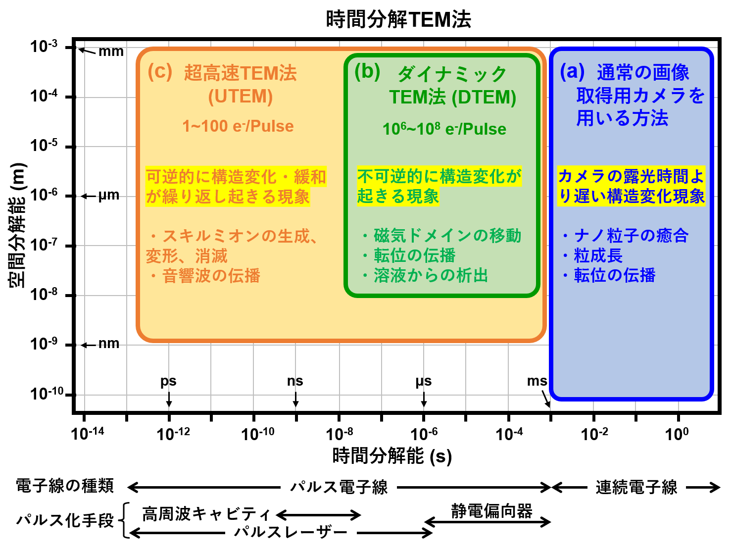
概念図: イメージングにおける時間分解能と空間分解能の相関
Time-resolved transmission electron microscopy (time-resolved TEM) is a method to perform time-series imaging for structural change of materials (specimens). In time-resolved TEM, various stimuli (e.g. heating, cooling, electric-magnetic field, tensile stress, laser irradiation) are applied to a specimen, and the resultant phenomena are subjected to time-series observation by using a continuous wave (CW) electron beam or a pulsed electron beam. The correlation between time resolution and spatial resolution in the imaging is shown in a conceptual diagram. In (descending) order of timescales of phenomena, the following three methods are used. (a) A method using a conventional imaging camera (Note 1) at a few seconds (s) to milliseconds (ms), (b) Dynamic TEM (DTEM) at ms to tens of nanoseconds (ns), and (c) Ultrafast TEM (UTEM) at ms to hundreds of femtoseconds (fs).
(a) Method using a conventional imaging camera
When the timescale of structural change of the specimen is slower than the minimum exposure time of a camera (about a few ms), time-resolved imaging can be performed with irradiation of a CW electron beam on the specimen. Time-resolved imaging can be achieved by setting the exposure time of a CMOS camera or a direct electron detection camera and recording the structural changes as a movie. The camera exposure time determines the time resolution. Thus, this method does not require highly-advanced techniques which synchronize stimuli against the specimen with the irradiated electron beam, as described in (b) and (c). For phenomena slower than a few ms, the method can be used for both reversible processes and irreversible processes.
(b) Dynamic TEM (DTEM)
Using DTEM, irreversible processes of structural change of a specimen can be imaged, which occur in the timescale of ms to tens of ns. Since the camera exposure time cannot capture the irreversible structural change in the timescale, a pulsed electron beam is used.
A pulsed electron beam is produced by blanking a CW electron beam using an electrostatic deflector, and by emission of pulsed photoelectrons obtained from irradiation of ultraviolet nanosecond pulsed lasers (wavelength: 250 to 350 nm, etc.) to a Ta cathode. The waiting time between the first and second pulses is called “pulse interval (repetition period)”. The pulse interval and the pulse width are determined by blanking speed (ms to tens of ns) and the type of pulsed laser (microseconds (µs) to tens of ns). To record irreversible changes into the camera with high signal-to-noise ratio, 106 to 108 electrons per pulse are required. The use of ultrahigh power pulsed lasers makes it possible to sustain 106 to 108 electrons even with a very-short pulsed electron beam of tens of ns. The time resolution is determined by the pulse interval and the pulse width.
Since DTEM needs to synchronize generation of a pulsed electron beam, stimuli to the specimen and camera exposure at a precision of ms to tens of ns, more advanced adjustment and data analysis are required than “method using a conventional imaging camera”.
For observing phenomena on the time scale of ms to µs, pulsed electrons blanked by electrostatic deflectors incorporated above the condenser lens are used. For phenomena occurring on timescales below 1 µs, pulsed electrons generated by photoemission from a laser are utilized. The number of pulse electron trains, each containing 10⁶ to 10⁸ electrons per pulse, depends on the laser output, and currently, up to 16 can be generated per 1 µs. In this case, the 16 pulse electron trains that have transmitted through the specimen are deflected in the X-Y direction (two-dimensionally) by electrostatic deflectors inserted above the image observation chamber, and 16 TEM images or electron diffraction patterns (arranged in a 4×4 grid) are recorded sequentially on a single frame of the camera. The size of each of the 16 images is determined by the size of the selected area aperture of the electrostatic deflectors and is set to occupy 1/16 of the single frame. From these 16 images, a frame-by-frame video is generated to observe structural changes in the sample.
(c) Ultrafast TEM (UTEM)
When the timescale of structural change of the specimen reaches ns to fs, the number of electrons per pulse becomes insufficient and thus, it is impossible to observe irreversible change processes. For reversible processes where structural change and relaxation occur repeatedly, the use of UTEM extends the timescale of the observed specimen to ms to fs. That is, UTEM is limited to observe such reversible processes.
In the case of UTEM, a pulsed electron beam is produced by emission of pulsed photoelectrons obtained from irradiation of ultraviolet femtosecond pulsed lasers (wavelength: 250 to 350 nm, etc.) to a Ta cathode, to a LaB6 cathode with a guard ring, or to a W (tungsten) cathode, and by chopping or blanking a CW electron beam using a high-frequency cavity or an electrostatic deflector. UTEM needs to synchronize generation of a pulsed electron beam, stimuli to the specimen and camera exposure at a high precision comparable to the pulse width (e.g. 1 picosecond (ps) to 200 fs).
The time resolution improves as the number of electrons decreases and the pulse width of the electron beam shortens, due to the Boersch effect. In other words, by keeping the laser output low and reducing the number of electrons per pulse to around 1 to 100, it is necessary to minimize the spatial spread (pulse width) of the pulsed electron beam along its propagation direction. In UTEM, the number of incident electrons to the specimen is small and the camera counts decrease. Therefore in some cases of image acquisition, by utilizing high repetition frequencies (kHz to MHz) of pulsed lasers, approximately one millions of images are superposed to improve signal-to-noise ratio.
[Note 1] This method is sometimes called “In-situ TEM”.
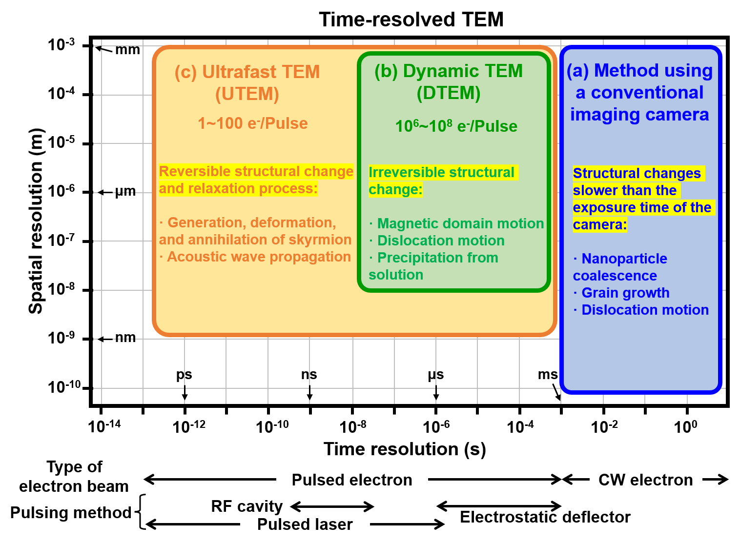
Conceptual diagram: Correlation between time resolution and spatial resolution in imaging
関連用語から探す
説明に「時間分解TEM法」が含まれている用語


