凹凸像
凹凸像
topographic image, BSE topographic image
[目次:理論]
試料表面の凹凸を示す反射電子像。
反射電子凹凸像は、入射電子に対して対称に置いた二つの検出器からの出力信号の差を取って得られる。通常、環状の半導体素子を2分割、もしくは4分割した、半導体ペア検出器が用いられる。
2分割した検出器では、相対して置かれた検出器と平行な方向に試料表面の傾斜が向いていると、その傾斜によるコントラストが付く。しかし、相対する検出器と直交する方向に試料表面の傾斜が向いている場合は、傾斜によるコントラストは付かない。この状況を図1(a)と(b)に示す。図1(c)に示すような4分割した検出器を使うと、検出素子AとBの組み合わせとCとDの組み合わせによるペア検出器およびそれらに直交する検出素子AとDの組み合わせとBとCの組み合わせによるペア検出器を作ることができる。この2通りの検出素子の組み合わせによって得られた画像を比較することで、試料表面のあらゆる方向の傾斜に対する見落としがなくなる。ただし、2分割の検出器でも、1枚の凹凸像の取得後に試料を機械的に約90°回転して凹凸像を取得し、この2枚の像を比較すれば、4分割検出器を使った場合と同じ結果を得ることができる。
なお、分割した検出器からの出力信号の和を取ると、凹凸のコントラストはなくなり、組成の違いによるコントラストを持つ組成像が得られる。
図2にダイヤモンド砥石の反射電子凹凸像と反射電子組成像を示す。凹凸像では、表面の微妙な凹凸差を見ることができる。組成像では、凹凸によるコントラストは消え、ダイヤモンドの粒子が黒く見え、組成を反映した像が得られる。
(a)は、試料表面の傾斜が、ペア検出器の配置と平行なため、凹凸のコントラストが付く。
(b)は、試料表面の傾斜が、ペア検出器の配置と直交方向なため、凹凸のコントラストは付かない。
加速電圧: 10kV, 試料: ダイヤモンド砥石
右図の凹凸像では、わずかな凹凸の差が鮮明に見える。左図の組成像では、反射電子放出率の小さいダイヤモンド粒子が黒く見えている。
"BSE topographic image" means a backscattered electron image which exhibits the topography of a specimen.
This image is obtained by the difference of the output signals from two detectors placed symmetrically against the incident (primary) electron beam. The commonly-used backscattered electron (BE) detector is a semiconductor pair detector that divides an annular semiconductor device into a pair of two segments or into a pair of four segments. For a two-segmented pair detector, when the specimen is inclined with respect to the direction parallel to the detector placement, the contrast due to the specimen inclination is produced. But when the specimen is inclined with respect to the direction perpendicular to the detector placement, no topographic contrast is produced. This principle is shown in Fig. 1(a) and (b). The use of a four-segmented pair detector (Fig. 1(c)) solves this problem. The four-segmented pair detector enables to make a pair detector which combines detector devices A and B, and C and D, and also to create a pair detector which combines A and D, and B and C. By combining these two pair detectors, the images taken with these two detectors are compared, enabling the observation of the topographic contrast of the specimen being inclined in any directions. However it should be noted that, even with the use of only the two-segmented pair detector, the same image taken with the four-segmented pair detector is obtained by mechanically rotating the specimen about 90 degrees to take a topographic image after one topographic image is acquired and then, by comparing these two images.
Adding the output signals from all segments results in the disappearance of the topographic contrast and instead, the compositional image due to the compositional difference in the specimen is obtained.
Fig. 2 shows a set of a BSE topographic image (right) and a BSE compositional image (left) of a diamond grindstone. In the right topographic image, the topographic details (very small difference in topography) of the specimen are observed. In the left compositional image, the topographic contrast disappears; but diamond particles appear dark (black) and the image formed by the compositional contrast is obtained.
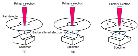
Fig.1 Relations between the directions of placement of pair detectors and the inclination of a specimen
(a) Since the specimen is inclined with respect to the direction parallel to the placement of the two-segmented pair detector, the topographic contrast is produced.
(b) Since the specimen is inclined with respect to the direction perpendicular to the placement of the two-segmented pair detector, no topographic contrast is produced.
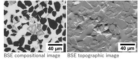
Fig.2 Comparison of BSE compositional image and BSE topographic image of a diamond grindstone, taken at an accelerating voltage of 10 kV.
In the right topographic image, the topographic details (very small difference in topography) are clearly observed. In the left compositional image, diamond particles are seen to be dark (black) because of a small backscattered electron emission coefficient of diamond.
関連用語から探す
説明に「凹凸像」が含まれている用語


